

Question: Write a VHDL description for the state- machine diagram for the batch mixing system derived in Example 4-10. Example 4-10: A mixing system for large
Write a VHDL description for the state- machine diagram for the batch mixing system derived in Example 4-10.
Example 4-10:
A mixing system for large batches of liquids is designed to add up to three ingredients to a large circular mixing tank, mix the ingredients, and then empty the mixed liquid from the tank. There are three inlets for ingredients, each with an on– off valve. There are three movable fluid sensors in the tank that can be set to turn off the respective valves at the level required for the first ingredient alone, for the first and second ingredients, and for all three ingredients. A switch is used to select either a two or three ingredient operation. There is a button for starting the operation and a second button for stopping the operation at any time. There is a timer for timing the mixing cycle. The length of the mixing cycle is specified by a manually operated dial that provides a starting value to a timer. The timer counts downward to zero to time the mixing. After mixing, the output valve is opened to remove the mixed liquid from the tank.
A sequential circuit is to be designed to control the batch mixing operation. The inputs and outputs for the circuit are given in Table 4-8. Before starting the operation of the mixing system, the operator places the fluid sensor L1, L2, and L3 in the proper locations. Next, the operator selects either two or three ingredients with switch NI and sets dial D to the mixing time. Then, the operator pushes the START to begin the mixing operation which proceeds automatically unless the STOP button is pushed. Valve V1 is opened and remains open until L1 indicates ingredient level 1 has been reached. Valve 1 closes and valve 2 opens and remains open until L2 indicates level 1 plus 2 has been reached. Valve 2 closes, and, if switch NI = 1, valve 3 opens and remains open until L3 indicates level 1, 2 plus 3 has been reached. If NI = 0, the value on dial D is then read into the timer, the mixing begins, and the timer starts counting down. In the case where NI = 1, these actions all occur when L3 indicates that the level for all three ingredients has been reached. When the timer reaches 0 as indicated by the signal TZ, the mixing stops. Next, the Output valve is opened and remains open until sensor L0 indicates the tank is empty. If STOP is pushed at any time, addition of ingredients stops, mixing stops, and the output valve closes.
Table 4-8:
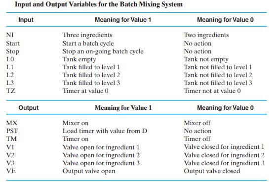
Input and Output Variables for the Batch Mixing System Input Meaning for Value 1 NI Start Stop LO L1 L2 L3 MX PST TM VI V2 Output V3 VE Three ingredients Start a batch cycle Stop an on-going batch cycle Tank empty Tank filled to level 1 Tank filled to level 2 Tank filled to level 3 Timer at value 0 Meaning for Value 1 Mixer on Load timer with value from D Timer on Valve open for ingredient 1 Valve open for ingredient 2 Valve open for ingredient 3 Output valve open Meaning for Value 0 Two ingredients No action No action Tank not empty Tank not filled to level 1 Tank not filled to level 2 Tank not filled to level 3 Timer not at value 0 Meaning for Value 0 Mixer off No action Timer off Valve closed for ingredient 1 Valve closed for ingredient 2 Valve closed for ingredient 3 Output valve closed
Step by Step Solution
3.53 Rating (160 Votes )
There are 3 Steps involved in it
Based on the given information we need to design a state machine in VHDL to control the batch mixing operation described in Example 410 The state mach... View full answer

Get step-by-step solutions from verified subject matter experts