

Question: There is a four - bit adder circuit called adder 4 that is configured as shown in ( Figure 2 ) , with inputs C
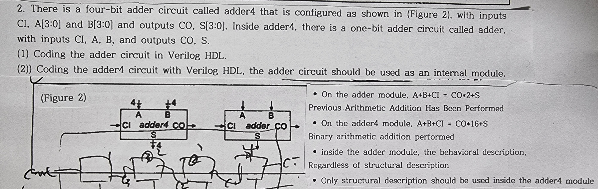
There is a fourbit adder circuit called adder that is configured as shown in Figure with inputs : and : and outputs : Inside adder there is a onebit adder circuit called adder, with inputs and outputs
Coding the adder circuit in Verilog HDL
Coding the adder circuit with Verilog HDL the adder circuit should be used as an internal module.
On the adder module,
Previous Arithmetic Addition Has Been Performed
On the adder module,
Binary arithmetic addition performed
inside the adder module, the behavioral description,
Regardless of structural description
Only structural description should be used inside the adder module
Step by Step Solution
There are 3 Steps involved in it
1 Expert Approved Answer
Step: 1 Unlock

Question Has Been Solved by an Expert!
Get step-by-step solutions from verified subject matter experts
Step: 2 Unlock
Step: 3 Unlock