

Question: Q1 Figure Q1 illustrates a multiple mass-spring-damper system. FL y Mass 1 2M 4K www 2C E y2 M M Mass 2 4M dy
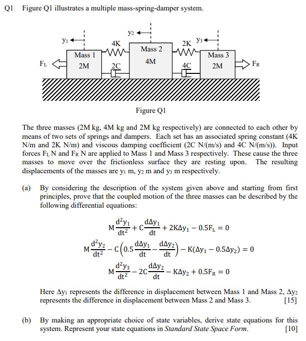
Q1 Figure Q1 illustrates a multiple mass-spring-damper system. FL y Mass 1 2M 4K www 2C E y2 M M Mass 2 4M dy dt Figure Q1 The three masses (2M kg, 4M kg and 2M kg respectively) are connected to each other by means of two sets of springs and dampers. Each set has an associated spring constant (4K N/m and 2K N/m) and viscous damping coefficient (2C N/(m/s) and 4C N/(m/s)). Input forces FL N and FR N are applied to Mass 1 and Mass 3 respectively. These cause the three masses to move over the frictionless surface they are resting upon. The resulting displacements of the masses are ym, y2 m and y3 m respectively. 2K www 4C (a) By considering the description of the system given above and starting from first principles, prove that the coupled motion of the three masses can be described by the following differential equations: I dy3 M- - 2C- dt Mass 3 2M day + C- +2KAY 0.5F = 0 dt day dt - FR dy-c(0.5 day day2) day2) - K(Ay - 0.5Ay) = 0 dt -KAY + 0.5FR = 0 Here Ay represents the difference in displacement between Mass 1 and Mass 2, Ay2 represents the difference in displacement between Mass 2 and Mass 3. [15] (b) By making an appropriate choice of state variables, derive state equations for this system. Represent your state equations in Standard State Space Form. [10]
Step by Step Solution
3.54 Rating (154 Votes )
There are 3 Steps involved in it
Considering the body and drawing FBD of the body first Slig... View full answer

Get step-by-step solutions from verified subject matter experts