

Question: Traffic Light Implement a circuit in Logisim for a standard traffic light that transitions as time passes. Follow these steps to build the circuit so
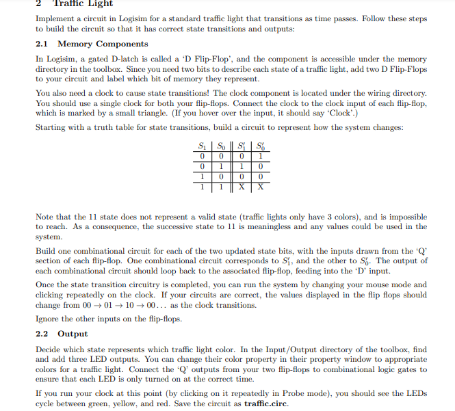
Traffic Light Implement a circuit in Logisim for a standard traffic light that transitions as time passes. Follow these steps to build the circuit so that it has correct state transitions and outputs: 2.1 Memory Components In Logisim, a gated D-latch is called a 'D Flip-Flop, and the component is accessible under the memory directory in the toolbox. Since you need two bits to describe each state of a traffic light, add two D Flip-Flops to your circuit and label which bit of memory they represent. You also need a clock to cause state transitions! The clock component is located under the wiring directory. You should use a single clock for both your flip-flops. Connect the clock to the clock input of each flip-flop, which is marked by a small triangle. (If you hover over the input, it should say 'Clock.) Starting with a truth table for state transitions, build a circuit to represent how the system changes: S. SO SS 0 0 1 1 0 1 0 1 0 1 0 X 1 0 0 Note that the 11 state does not represent a valid state (traffic lights only have 3 colors), and is impossible to reach. As a consequence, the successive state to 11 is meaningless and any values could be used in the system. Build one combinational circuit for each of the two updated state bits, with the inputs drawn from the 'Q% section of each flip-flop. One combinational circuit corresponds to S1, and the other to S. The output of each combinational circuit should loop back to the associated flip-flop, feeding into the 'D' input. Once the state transition circuitry is completed, you can run the system by changing your mouse mode and clicking repeatedly on the clock. If your circuits are correct, the values displayed in the flip flops should change from 00 01 1000... as the clock transitions. Ignore the other inputs on the flip-flops. 2.2 Output Decide which state represents which traffic light color. In the Input/Output directory of the toolbox, find and add three LED outputs. You can change their color property in their property window to appropriate colors for a traffic light. Connect the "Q outputs from your two flip-flops to combinational logic gates to ensure that each LED is only turned on at the correct time. If you run your clock at this point (by clicking on it repeatedly in Probe mode), you should see the LEDs cycle between green, yellow, and red. Save the circuit as traffic.circ
Step by Step Solution
There are 3 Steps involved in it

Get step-by-step solutions from verified subject matter experts