

Question: USE ADRESS BIT WIDTH AS 3 AND DATA BIT WIDTH AS 6 IN LOGISIM Use a Logisim ROM to implement the State Table. Configure the
USE ADRESS BIT WIDTH AS 3 AND DATA BIT WIDTH AS 6 IN LOGISIM
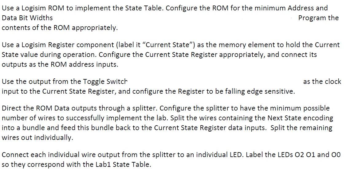
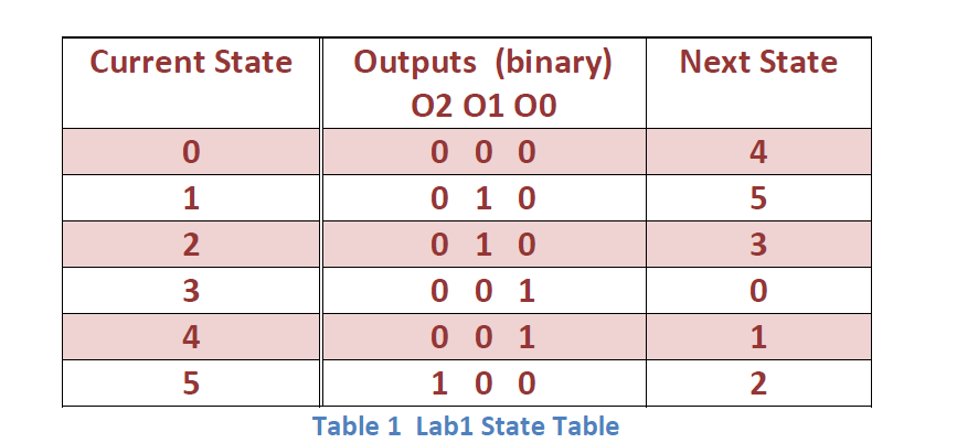
Use a Logisim ROM to implement the State Table. Configure the ROM for the minimum Address and Data Bit Widths Program the contents of the ROM appropriately. Use a Logisim Register component (label it Current State) as the memory element to hold the Current State value during operation. Configure the Current State Register appropriately, and connect its outputs as the ROM address inputs. as the clock Use the output from the Toggle Switch input to the Current State Register, and configure the Register to be falling edge sensitive. Direct the ROM Data outputs through a splitter. Configure the splitter to have the minimum possible number of wires to successfully implement the lab. Split the wires containing the Next State encoding into a bundle and feed this bundle back to the Current State Register data inputs. Split the remaining wires out individually. Connect each individual wire output from the splitter to an individual LED. Label the LEDs 02 01 and 00 so they correspond with the Labi State Table. Current State Next State 0 4 1 5 2 Outputs (binary) 02 01 00 0 0 0 0 1 0 0 1 0 0 0 1 0 0 1 1 0 0 Table 1 Labi State Table 3 3 0 1 4 5 2 Use a Logisim ROM to implement the State Table. Configure the ROM for the minimum Address and Data Bit Widths Program the contents of the ROM appropriately. Use a Logisim Register component (label it Current State) as the memory element to hold the Current State value during operation. Configure the Current State Register appropriately, and connect its outputs as the ROM address inputs. as the clock Use the output from the Toggle Switch input to the Current State Register, and configure the Register to be falling edge sensitive. Direct the ROM Data outputs through a splitter. Configure the splitter to have the minimum possible number of wires to successfully implement the lab. Split the wires containing the Next State encoding into a bundle and feed this bundle back to the Current State Register data inputs. Split the remaining wires out individually. Connect each individual wire output from the splitter to an individual LED. Label the LEDs 02 01 and 00 so they correspond with the Labi State Table. Current State Next State 0 4 1 5 2 Outputs (binary) 02 01 00 0 0 0 0 1 0 0 1 0 0 0 1 0 0 1 1 0 0 Table 1 Labi State Table 3 3 0 1 4 5 2
Step by Step Solution
There are 3 Steps involved in it

Get step-by-step solutions from verified subject matter experts