

Question: using circuitverse please show me and explain how to draw the circuit for a door opener and simulate its operations. In this tutorial, we will
using circuitverse please show me and explain how to draw the circuit for a door opener and simulate its operations.
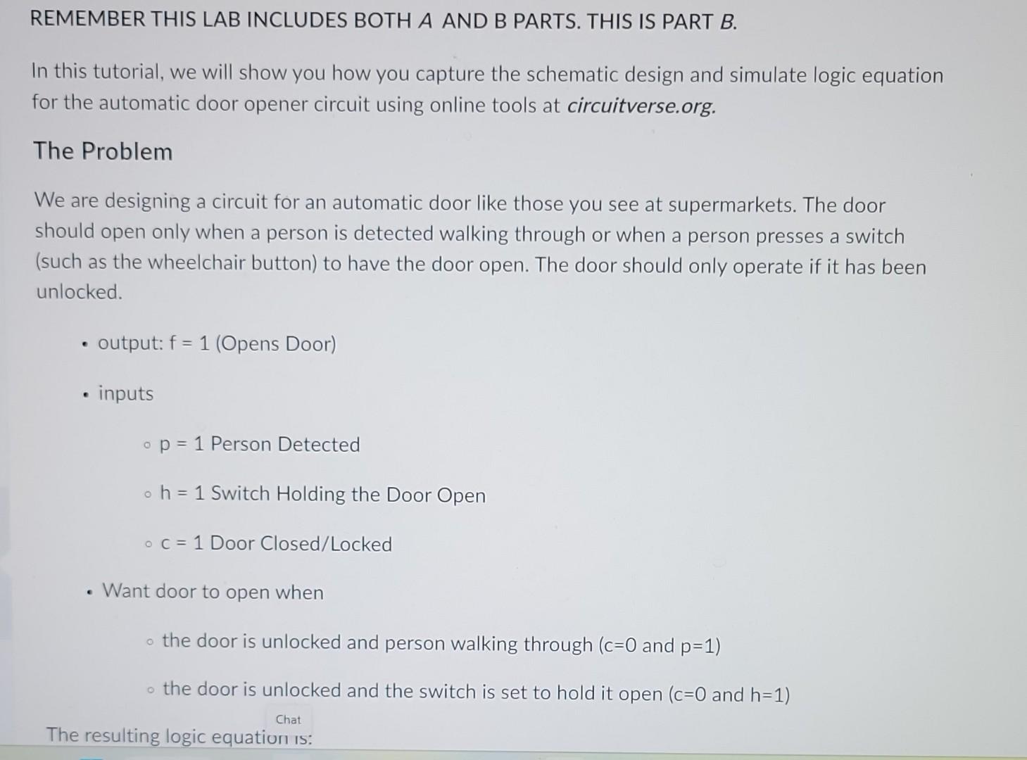
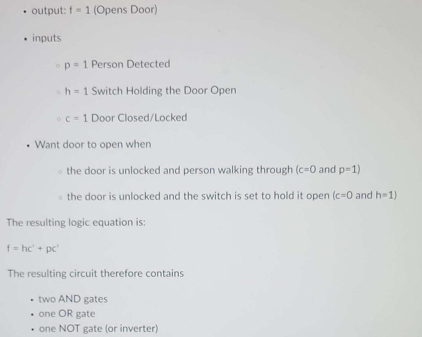
In this tutorial, we will show you how you capture the schematic design and simulate logic equation for the automatic door opener circuit using online tools at circuitverse.org. The Problem We are designing a circuit for an automatic door like those you see at supermarkets. The door should open only when a person is detected walking through or when a person presses a switch (such as the wheelchair button) to have the door open. The door should only operate if it has been unlocked. - output: f=1 (Opens Door) - inputs - p=1 Person Detected h=1 Switch Holding the Door Open - c=1 Door Closed/Locked - Want door to open when - the door is unlocked and person walking through (c=0 and p=1) the door is unlocked and the switch is set to hold it open (c=0 and h=1 ) - output: f=1 (Opens Door) - inputs p=1 Person Detected h=1 Switch Holding the Door Open c=1 Door Closed/Locked - Want door to open when the door is unlocked and person walking through (c=0 and p=1 ) the door is unlocked and the switch is set to hold it open ( c=0 and h=1 ) The resulting logic equation is: f=hc+pc The resulting circuit therefore contains - two AND gates - one OR gate - one NOT gate (or inverter)
Step by Step Solution
There are 3 Steps involved in it

Get step-by-step solutions from verified subject matter experts