

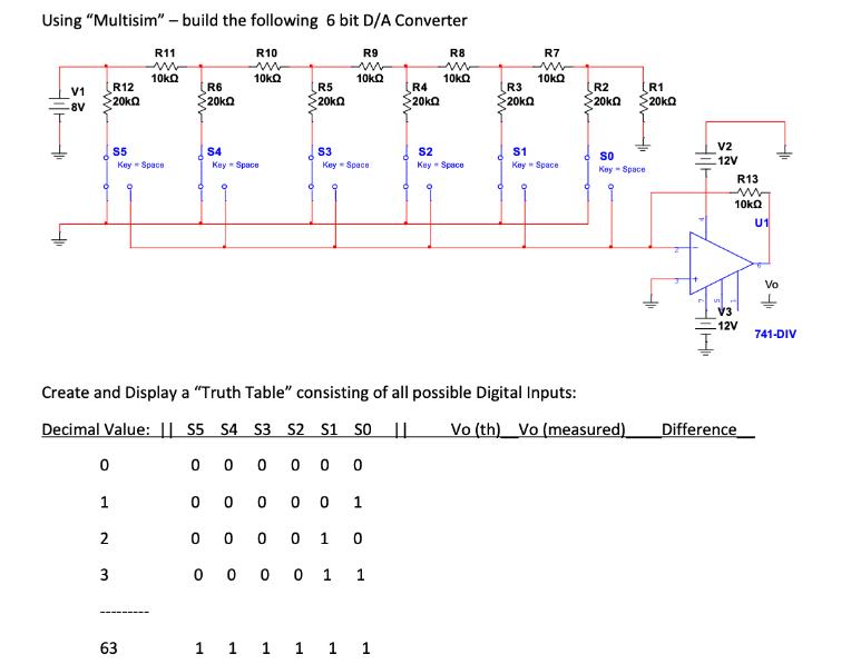
Question: Using Multisim - build the following 6 bit D/A Converter Hi V1 -8V R12 - 20k 0 1 2 3 R11 ww 10kQ S5
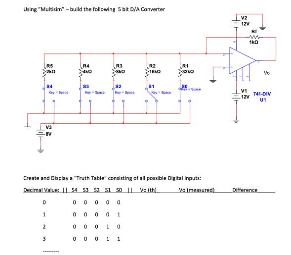 2kQ V3 8V 0 1 S4 2 3 Key Space R4 >4kQ S3">
Using "Multisim" - build the following 6 bit D/A Converter Hi V1 -8V R12 - 20k 0 1 2 3 R11 ww 10kQ S5 Key Space 63 R6 20k R10 www 10kQ 0 S4 Key Space R5 20k S3 R9 ww 10kQ KeySpace 0 0000 1 0 0 0 1 0 0 000 1 1 R4 >20k 1 1 1 1 1 1 R8 ww 10kQ Create and Display a "Truth Table" consisting of all possible Digital Inputs: Decimal Value: S5 S4 S3 S2 S1 SO | Vo (th) Vo (measured) 000000 S2 Key Space R3 20k R7 ww 10kQ S1 KeySpace R2 >20k 55 Key - Space R1 20kQ V2 12V R13 ww 10kQ U1 V3 12V Difference Vo 741-DIV Using "Multisim"- build the following 5 bit D/A Converter LIH R5 >2kQ V3 8V 0 1 S4 2 3 Key Space R4 >4kQ S3 Key = Space 00 R3 >8kQ S2 Key = Space 0 O Create and Display a "Truth Table" consisting of all possible Digital Inputs: Decimal Value: S4 S3 S2 S1 SO | Vo (th) Vo (measured) 0 0 0 0 0 0 0 1 0 0 1 0 0 0 0 1 1 R2 16k0 $1 Key = Space R1 >32kQ SO Rey-Space V2 12V Rf m 1kQ V1 -12V Vo 741-DIV U1 Difference
Step by Step Solution
3.33 Rating (153 Votes )
There are 3 Steps involved in it
It appears that youve shared schematics for 6bit and 5bit DigitaltoAnalog Converters DACs using resistor ladders R2R ladder network and a single operational amplifier opamp The schematic diagrams show ... View full answer

Get step-by-step solutions from verified subject matter experts