

Question: Using Verilog code, please explain how it all comes together in the code. : A synchronous counter can be designed by using master-slave JK flipflops.
Using Verilog code, please explain how it all comes together in the code.
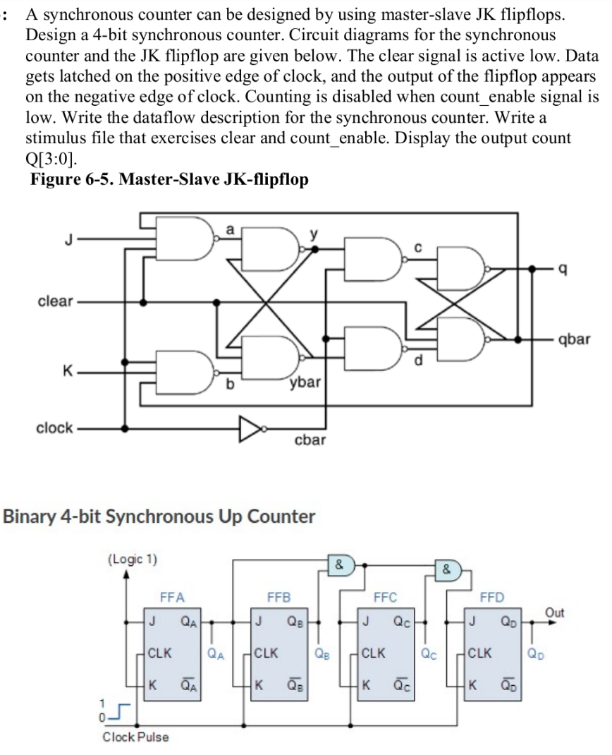
: A synchronous counter can be designed by using master-slave JK flipflops. Design a 4-bit synchronous counter. Circuit diagrams for the synchronous counter and the JK flipflop are given below. The clear signal is active low. Data gets latched on the positive edge of clock, and the output of the flipflop appears on the negative edge of clock. Counting is disabled when count_enable signal is low. Write the dataflow description for the synchronous counter. Write a stimulus file that exercises clear and count_enable. Display the output count Q[3:0). Figure 6-5. Master-Slave JK-flipflop a J 9 clear qbar b ybar clock cbar Binary 4-bit Synchronous Up Counter (Logic 1) & & FFA FFB FFC FFD Out J QA J QB J Qc J Qp T CLK QA CLK Qe CLK Qc HCLK K QA K Qc Clock Pulse
Step by Step Solution
There are 3 Steps involved in it

Get step-by-step solutions from verified subject matter experts