

Question: V. Consider the following assembly language code 10: ADD R4R1+ RO; 11: SUB R9 R3- R4: 12: ADD R4 R5R6: 13: LDW R2 = MEM[R3
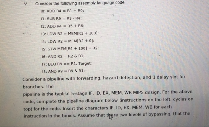
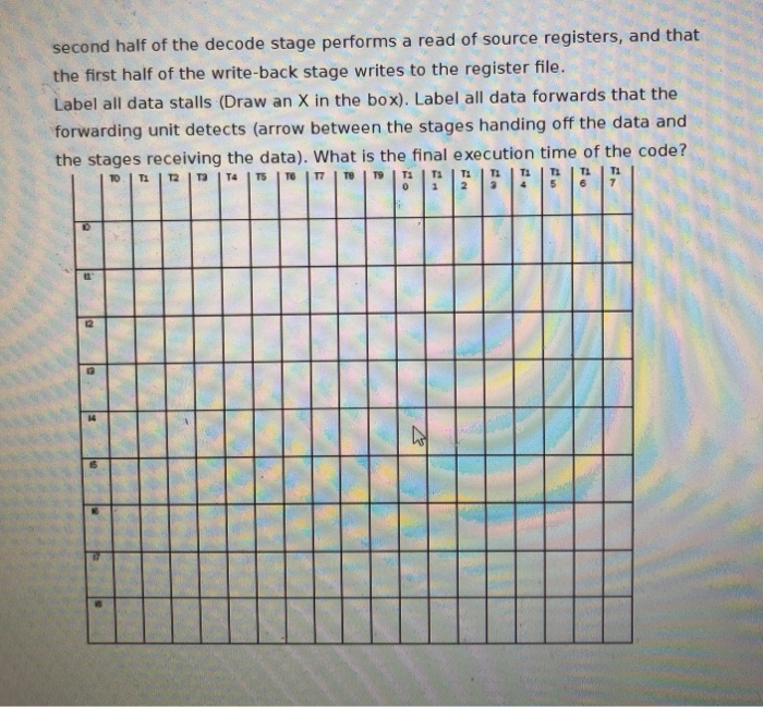
V. Consider the following assembly language code 10: ADD R4R1+ RO; 11: SUB R9 R3- R4: 12: ADD R4 R5R6: 13: LDW R2 = MEM[R3 + 100); A: LDW R2 = MEM[R2 + 0]; 15: STW MEMIR4 + 100] R2: 16: AND R2 R2 & R1; 17: BEQ R9 == R1. Target; 18: AND R9 = R9 & R1; Consider a pipeline with forwarding, hazard detection, and 1 delay slot for branches. The pipeline is the typical 5-stage IF, ID, EX, MEM, WB MIPS design. For the above code, complete the pipeline diagram below (instructions on the left, cycles on top) for the code. Insert the characters IF, ID, EX, MEM, WB for each instruction in the boxes. Assume that there two levels of bypassing, that the
Step by Step Solution
There are 3 Steps involved in it

Get step-by-step solutions from verified subject matter experts