

Question: We are using a TM4C123G launchpad EECE237 Homework 2: 3-bit Binary Counter The objective is to build a three bit counter with the Tiva board.
We are using a TM4C123G launchpad
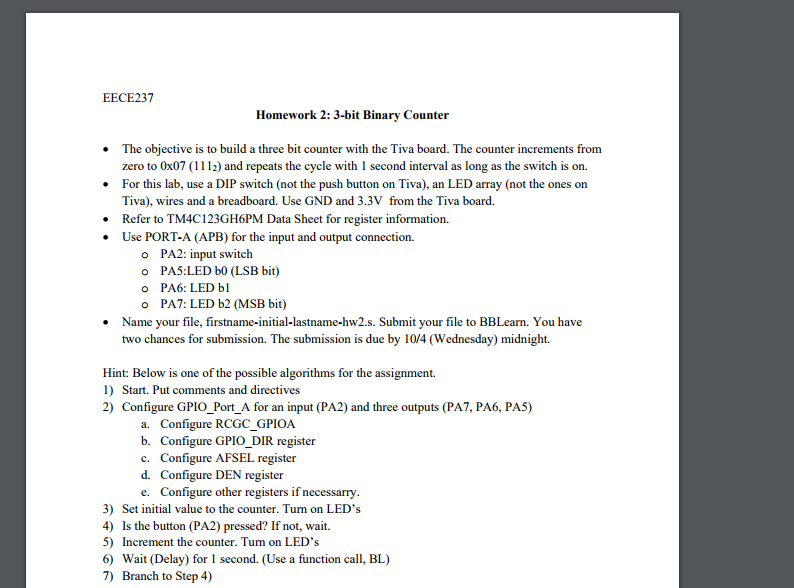
EECE237 Homework 2: 3-bit Binary Counter The objective is to build a three bit counter with the Tiva board. The counter increments from zero to 0x07 (1112) and repeats the cycle with 1 second interval as long as the switch is on. For this lab, use a DIP switch (not the push button on Tiva), an LED array (not the ones on Tiva), wires and a breadboard. Use GND and 3.3V from the Tiva board. Refer to TM4C123GH6PM Data Sheet for register information. Use PORT-A (APB) for the input and output connection. o o o o PA2: input switch PAS:LED bo (LSB bit) PA6: LED bl PA7: LED b2 (MSB bit) Name your file, firstname-initial-lastname-hw2.s. Submit your file to BBLearn. You have two chances for submission. The submission is due by 10/4 (Wednesday) midnight. Hint: Below is one of the possible algorithms for the assignment. 1) Start. Put comments and directives 2) Configure GPIO_Port_A for an input (PA2) and three outputs (PA7, PA6, PA5) a. Configure RCGC GPIOA b. Configure GPIO DIR register Configure AFSEL register c. d. Configure DEN register e. Configure other registers if necessarry 3) Set initial value to the counter. Turn on LED's Is the button (PA2) pressed? If not, wait. 4) 5) Increment the counter. Turn on LED's 6) Wait (Delay) for 1 second. (Use a function call, BL) 7) Branch to Step 4) EECE237 Homework 2: 3-bit Binary Counter The objective is to build a three bit counter with the Tiva board. The counter increments from zero to 0x07 (1112) and repeats the cycle with 1 second interval as long as the switch is on. For this lab, use a DIP switch (not the push button on Tiva), an LED array (not the ones on Tiva), wires and a breadboard. Use GND and 3.3V from the Tiva board. Refer to TM4C123GH6PM Data Sheet for register information. Use PORT-A (APB) for the input and output connection. o o o o PA2: input switch PAS:LED bo (LSB bit) PA6: LED bl PA7: LED b2 (MSB bit) Name your file, firstname-initial-lastname-hw2.s. Submit your file to BBLearn. You have two chances for submission. The submission is due by 10/4 (Wednesday) midnight. Hint: Below is one of the possible algorithms for the assignment. 1) Start. Put comments and directives 2) Configure GPIO_Port_A for an input (PA2) and three outputs (PA7, PA6, PA5) a. Configure RCGC GPIOA b. Configure GPIO DIR register Configure AFSEL register c. d. Configure DEN register e. Configure other registers if necessarry 3) Set initial value to the counter. Turn on LED's Is the button (PA2) pressed? If not, wait. 4) 5) Increment the counter. Turn on LED's 6) Wait (Delay) for 1 second. (Use a function call, BL) 7) Branch to Step 4)
Step by Step Solution
There are 3 Steps involved in it

Get step-by-step solutions from verified subject matter experts