

Question: Write a verilog code The following circuit represents a simple 16-bit Arithmetic and Logic Unt (ALU) that has two 16-bit inputs, X, and Y, and
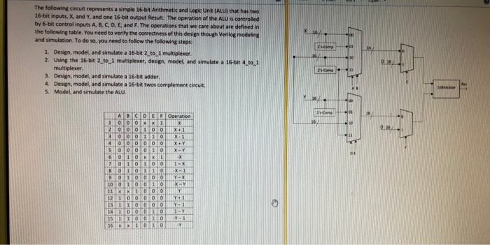
The following circuit represents a simple 16-bit Arithmetic and Logic Unt (ALU) that has two 16-bit inputs, X, and Y, and one 16-bit output Result The operation of the ALU is controlled by 6-bit control inputs A, BC, D, E, and F The operations that we care about are defined in the following table. You need to verify the correctness of this and simulation. To do so, you need to follow the following steps design though Veriloe modelieg 1. Design, model, and simulate a 16-bit 2 to 1 multiplexer 2. Using the 16-bit 2 to 1 multiplexer, design, model, and simulate a 16-bit 4 to Design, model, and simulate a 16-bit adder. Design, model, and simulate a 16-bit twos complement circuit. Model and simulate the ALU 3. 4. S. The following circuit represents a simple 16-bit Arithmetic and Logic Unt (ALU) that has two 16-bit inputs, X, and Y, and one 16-bit output Result The operation of the ALU is controlled by 6-bit control inputs A, BC, D, E, and F The operations that we care about are defined in the following table. You need to verify the correctness of this and simulation. To do so, you need to follow the following steps design though Veriloe modelieg 1. Design, model, and simulate a 16-bit 2 to 1 multiplexer 2. Using the 16-bit 2 to 1 multiplexer, design, model, and simulate a 16-bit 4 to Design, model, and simulate a 16-bit adder. Design, model, and simulate a 16-bit twos complement circuit. Model and simulate the ALU 3. 4. S
Step by Step Solution
There are 3 Steps involved in it

Get step-by-step solutions from verified subject matter experts