

Question: Clock Clear Fig. A.2: Two Digit BCD Counter - BCDCount2 Enable Do D D D3 Load Clock Enable Do D D D3 Load Clock
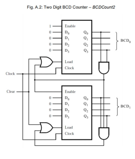
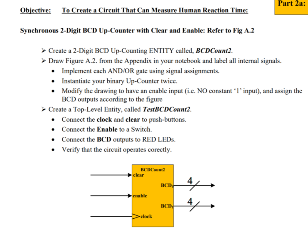
Clock Clear Fig. A.2: Two Digit BCD Counter - BCDCount2 Enable Do D D D3 Load Clock Enable Do D D D3 Load Clock Qo Q Q Q3 Qo Q Q Q3 BCD, BCD Objective: To Create a Circuit That Can Measure Human Reaction Time: Synchronous 2-Digit BCD Up-Counter with Clear and Enable: Refer to Fig A.2 Create a 2-Digit BCD Up-Counting ENTITY called, BCDCount2. Draw Figure A.2. from the Appendix in your notebook and label all internal signals. Implement each AND/OR gate using signal assignments. Instantiate your binary Up-Counter twice. Modify the drawing to have an enable input (i.e. NO constant '1' input), and assign the BCD outputs according to the figure Create a Top-Level Entity, called TestBCDCount2. Connect the clock and clear to push-buttons. Connect the Enable to a Switch. Connect the BCD outputs to RED LEDs. Verify that the circuit operates corectly. BCDCount2 clear enable clock BCD BCD Part 2a: 4/ 4/
Step by Step Solution
3.39 Rating (149 Votes )
There are 3 Steps involved in it

Get step-by-step solutions from verified subject matter experts