

Question: x=50 PART A 140 points| The feed water system shown in the figure below is for a pressure tank. The feed water pump is to
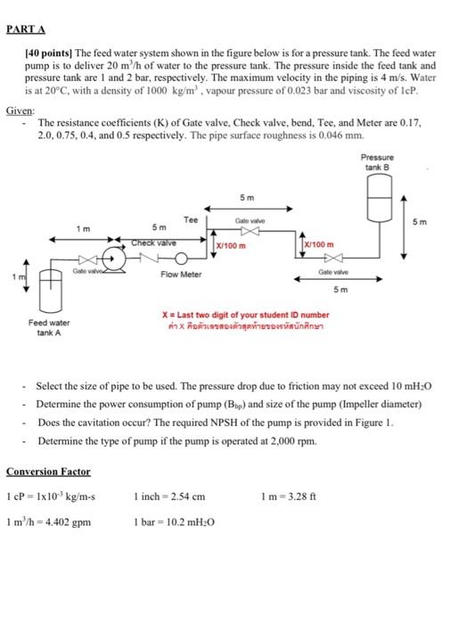
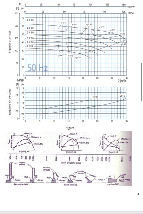
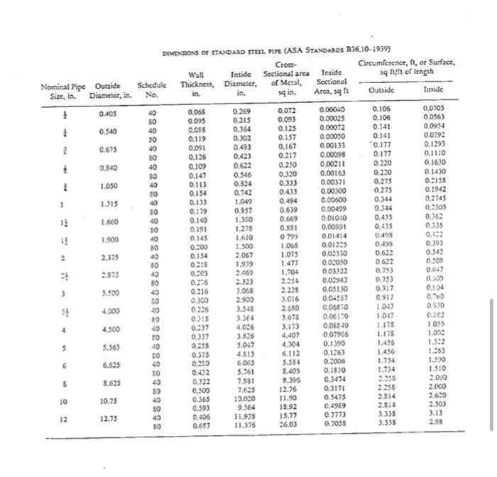
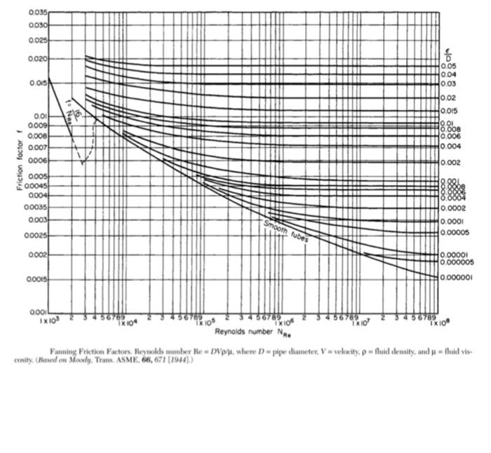
PART A 140 points| The feed water system shown in the figure below is for a pressure tank. The feed water pump is to deliver 20 m/h of water to the pressure tank. The pressure inside the feed tank and pressure tank are 1 and 2 bar, respectively. The maximum velocity in the piping is 4 m/s. Water is at 20C, with a density of 1000 kg/ml vapour pressure of 0.023 bar and viscosity of IcP. Given: The resistance coefficients (K) of Gate valve, Check valve, bend, Tee, and Meter are 0.17, 2.0.0.75, 0.4, and 0.5 respectively. The pipe surface roughness is 0.046 mm. Pressure tank B 5 m Tee Gateway 1 m 5 m 5 m Check valve X/100 m x 100 m Gate Flow Meter Gate Valve 5 m Feed water X = Last two digit of your student ID number X tank A - Select the size of pipe to be used. The pressure drop due to friction may not exceed 10 mH:0 - Determine the power consumption of pump (Bup) and size of the pump (Impeller diameter) Does the cavitation occur? The required NPSH of the pump is provided in Figure 1. Determine the type of pump if the pump is operated at 2,000 rpm. Conversion Factor 1 CP = 1x10 kg/m-s 1 inch - 2.54 cm 1 m=3.28 ft 1 m/h = 4.402 gpm 1 bar = 10.2 mH:0 3 50 5 100 125 150 USGPM To 70% os 75 125 100 GPU 70 0210 20060 3045 Impeller diameter 0200 50 0190 150 0130 400170 0160 100 30 20 SON 50 10 50HZ 0 0 0 5 10 15 20 > 30 NPSH IN Im 10 3 walo 75 25 2 160 0210 Required NPSH-value 5 15 1 25 05 0 0 10 15 Figure 1 - N ceny efficiency.beat need -werthe CRO -0051 or 5.000 6.000 1.000 9.000 10.000 15.000 shred I Vanes Vanes sqin. Nominal Pipe Outside Size, in. Diameter, in. 0.405 0.540 2 0.675 0.840 + 2 1.050 1 1.315 0.179 11 1.600 1.900 DIMENSIONS OF STANDARD STEEL PIPE (ASA STANDARDS B36.10-1939) Cross- Circumference, ft, or Surface, Wall Inside Sectional area Inside sq ft of length Schedule Thickness, Diameter, of Metal Sectional No. in. Arca, sqft Outside Inside 40 0.068 0.269 0.072 0.00040 0.106 0.0705 80 0.095 0.215 0.093 0.00025 0.106 0.0563 40 0.088 0.354 0.125 0.00072 0.141 0.0954 90 0.119 0.302 0.157 0.00050 0.141 0.0792 40 0.091 0.493 0.167 0.00133 *0.177 0.1293 80 0.126 0.423 0.217 0.00098 0.177 0.1110 40 0.109 0.622 0.250 0.00211 0.220 0.1630 50 0.147 0.546 0.320 0.0016) 0.220 0.1430 40 0.113 0.824 0.333 0.00371 0.275 0.3158 80 0.154 0.742 0.433 0.00300 0.275 0.1942 40 0.133 1.049 0.494 0.00600 0.344 0.2745 50 0.957 0.639 0.00499 0.344 0.2505 40 0.140 1.350 0.669 0.01040 0.435 0.362 SO 0.191 1.278 0.581 0.00891 0.435 0.335 40 0.145 1.610 0799 0.01414 0.498 80 0.300 1.500 1.065 0.01235 0.498 0.393 40 0.154 2.067 1.075 0.02350 0.622 0.542 80 0.216 1.939 1.477 0.02050 0.622 0.S08 40 0.103 2.469 1.704 0.03322 0.753 0.647 80 02:6 2.323 2.254 0.02942 0.753 0.00 49 0.216 3.068 2.225 0.05130 0.217 0.104 50 0.300 2.900 3.016 0.04957 0.917 0.700 20 0.226 3.545 2.680 0.06870 1.047 0.930 0.315 3.364 3.678 0.0610 0582 0.237 4,026 3.173 0.05540 1.278 1.055 20 0.337 3.826 4,407 0.07956 1.175 1.000 40 0.238 5.047 4.304 0.1390 1.456 30 0.375 4.813 6.112 0.1263 40 0.250 6.065 5.55 0.2006 1.734 1.590 SO 0.432 5.761 8.405 0.1810 1.510 40 0.322 7.981 8.395 0.3474 2.090 50 0.500 7.625 12.76 0.3171 2.358 2.000 40 0.365 10.000 11.90 0.5475 2814 2.650 SO 0.593 9.564 13.92 0.4989 2.814 2.503 40 0.406 11.938 15.77 0.7773 3.338 80 11.376 26.03 0.7058 2.98 2.375 2.875 3.500 3 4.000 10:2 4.300 5.563 6 6.625 $ 8.625 10 10.75 12 12.75 0.687 3.3.38 0.035 0030 0025 00201 16 o. OiN 005 0.04 0.03 10.02 0.015 88 OL 0.008 0.006 0.004 0.00 2009! 0.008) 0.007 0006) Friction foctor 0.002 0005 00045 2004 00035) 0.003 Smooth tubes 0.0002 0.0001 0.00005 00025 0002H 0.00001 0.000005 0.000001 000ish IX100 0001 X106 Reynolds number No. Fanning Friction Factors. Reynolds mmber Re - DVpju, where D-pipe diameter, V-velocity, p-fluiel density, and u = fluid vis. cosity. Based on Money Trans ASME, 66, 671 [1984])
Step by Step Solution
There are 3 Steps involved in it

Get step-by-step solutions from verified subject matter experts