

Question: Your goal with this design problem is to specify all the components of a small hydrostatic transmission for a hydraulic powered go kart with regenerative
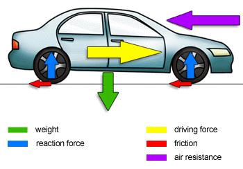
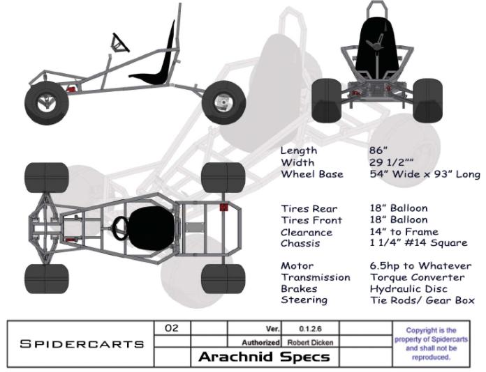
Your goal with this design problem is to specify all the components of a small hydrostatic transmission for a hydraulic powered go kart with regenerative breaking. The go kart will be assumed to be 150 kg and the prime mover is a 15 kW electric motor. The torque needed to move the vehicle is found by drawing a free body diagram of the vehicle and estimating the driving force. Neglect the air resistance and assume the friction coefficient to be 0.08 for driving on asphalt. You want the vehicle to reach a speed of 50 mph in 8 seconds and the maximum system pressure to be 3500 psi.
1:Select (specify size and brand) the following components:
- Accumulator: To regenerate power from breaking. The accumulator must be able to launch the vehicle from a stand-still to at least 30 mph.
- Relief valve: To maintain safety from the hydraulic system at all the times
- Directional control valves: To control the opening and closing of the accumulator, and another DCV to control forward, reverse motion of the vehicle.
- Hydraulic Pump: To propel the vehicle, the pump is directly attached to the electric motor but can also use a gearbox if necessary.
- Hydraulic motor: To turn the drive shaft of the vehicle
- Check Valve: To prevent flow from accumulator from going into the pump
- Hose sizes: Specify the size of the hose or tubing you will be using
- Filter type and cleanliness specification
- Hydraulic reservoir size
- Hydraulic oil to be used including (Viscosity grade and VI)
All the components selected from the list need to be justified in a single page using an explanatory text. One page that describes how you selected these components. Does not matter font size or number of words, do what you need to do to justify your selections.
2:Hydraulic circuit schematic
Elaborate a circuit schematic following ISO symbols of the proposed hydraulic go-kart. The schematic must include the components in the list of grading criteria 1. Use a computer program like Microsoft Visio, Automation Studio, Simhydraulics (Matlab) or similar, to create your schematic. No hand-drawn schematics will be accepted.
. 3: Calculations:
All of your selected components must be backed by analytical calculations that demonstrate the feasibility of your design. For example: pump size is determined by the required flow and pressure that your system needs. Your calculations must derive from an initial free body diagram of the vehicle and the appropriate equation of motion from Newton’s second law.
. 4:Presentation of the document and conclusions. The cleaner and better presented of a report the better your grade for this criteria is going to be. I want you to be able to reflect and demonstrate the things that you learn during the class and in this project.
5:Create a block diagram from the flow equations controlling the hydraulic motor. That is, the pump flow through the DCV into the hydraulic motor. Must include motor inertia or at least inertia of the wheels, driving force (torque) and friction.
+ weight reaction force driving force friction air resistance
Step by Step Solution
3.38 Rating (160 Votes )
There are 3 Steps involved in it
Design Problem Solution 1 Selection of Components Accumulator The accumulator must be able to launch the vehicle from a standstill to at least 30 mph To calculate the required accumulator size we can ... View full answer

Get step-by-step solutions from verified subject matter experts