New Semester
Started
Get
50% OFF
Study Help!
--h --m --s
Claim Now
Question Answers
Textbooks
Find textbooks, questions and answers
Oops, something went wrong!
Change your search query and then try again
S
Books
FREE
Study Help
Expert Questions
Accounting
General Management
Mathematics
Finance
Organizational Behaviour
Law
Physics
Operating System
Management Leadership
Sociology
Programming
Marketing
Database
Computer Network
Economics
Textbooks Solutions
Accounting
Managerial Accounting
Management Leadership
Cost Accounting
Statistics
Business Law
Corporate Finance
Finance
Economics
Auditing
Tutors
Online Tutors
Find a Tutor
Hire a Tutor
Become a Tutor
AI Tutor
AI Study Planner
NEW
Sell Books
Search
Search
Sign In
Register
study help
sciences
fundamentals electric circuits
Fundamentals of Electric Circuits 6th edition Charles K Alexander, Matthew Sadiku - Solutions
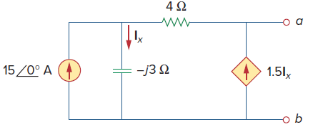
Find the Thevenin equivalent at terminals a€‘b of the circuit inFig. 10.104. 4Ω -j3 2 15/0° A 1.51, -o b
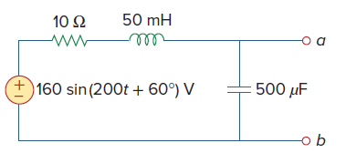
Obtain the Norton equivalent of the circuit depicted inFig. 10.106 at terminals a€‘b. 10 Ω 50 mH ell +)160 sin (200t + 60°) V 500 µF
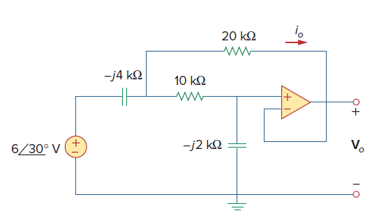
Determine Voand Ioin the op amp circuit ofFig. 10.119. 20 k2 -j4 k2 10 k2 -j2 k2 V. 6/30° V Q+
If v(t) = 160 cos 50t V and i(t) = −33 sin (50t − 30°)A, calculate the instantaneous power and the average power.
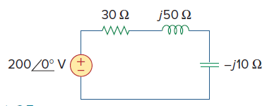
Given the circuit inFig. 11.35, find the average power supplied or absorbed by each element. 30 Ω j50 2 200/0° V (+ -10 Ω
A load consists of a 60-Ω resistor in parallel with a 90-μF capacitor. If the load is connected to a voltage source vs(t) = 160 cos 2000t, find the average power delivered to the load
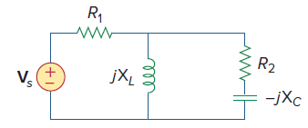
UsingFig. 11.36, design a problem to help other students better understand instantaneous and average power.Find the average power dissipated by the resistances in the circuit of Fig. 11.36. Additionally, verify the conservation of power. R, R2 jXL V. -jXc +1
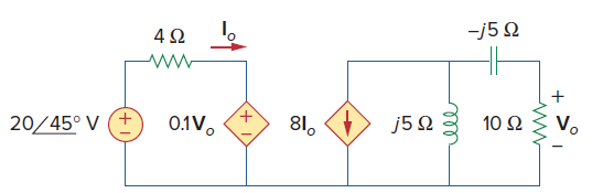
For the circuit inFig. 11.38, is= 6 cos 103t A. Find the average power absorbed by the 50-Ω resistor. 15Ω 4Ω Νο 10 Ω 81. J5 Ω 20/45ο V (+ 0.1V.
The Thevenin impedance of a source is ZTh = 120 + j60 Ω, while the peak Thevenin voltage is VTh = 165 + j0 V. Determine the maximum available average power from the source.
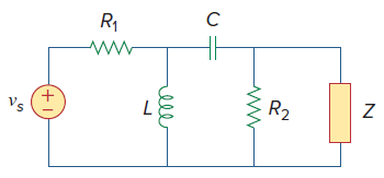
UsingFig. 11.45, design a problem to help other students better understand maximum average power transfer to a load Z.It is desired to transfer maximum power to the load Z in the circuit shown below. Find Z and the maximum average power. Let vs = 100 sin(100t) V. R1 R2 Vs ell
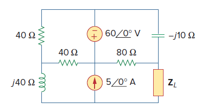
Find the value of ZLin the circuit ofFig. 11.49 for maximum power transfer. 60/0° V 40 2 -j10 2 40 2 80 2 5/0° A ZL j40 2
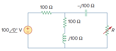
The variable resistor R in the circuit ofFig. 11.50 is adjusted until it absorbs the maximum average power. Find R and the maximum average power absorbed. -j100 2 100 2 100 2 100/0° V (+ j100 2 lle
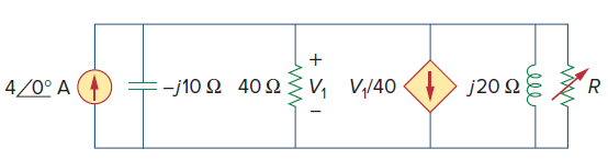
The load resistance RLinFig. 11.51 is adjusted until it absorbs the maximum average power. Calculate the value of RLand the maximum average power. > 120 Ω .-j10 Ω 40 Ω
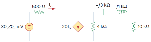
Obtain the complex power delivered to the 10-kΩ resistor inFig. 11.77 below. -13 ΚΩ j1 ΚΩ 500 Ω ο 0η 10 kΩ 30 /0° mV (+ 201, 4 ΚΩ
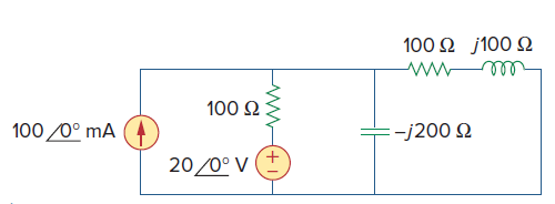
Calculate the reactive power in the inductor and capacitor in the circuit ofFig. 11.78. j100 Ω 100 Ω 100 2 100 /0° mA :-j200 2 20/0° V (
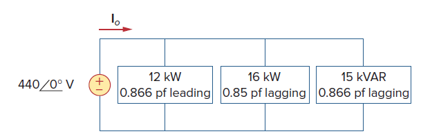
Find Ioin the circuit ofFig. 11.82. 12 kW 16 kW 15 KVAR 440/0° V 0.866 pf leading 0.85 pf lagging 0.866 pf lagging
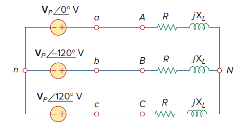
UsingFig. 12.41, design a problem to help other students better understand balanced wye-wye connected circuits.For the Y-Y circuit of Fig. 12.41, find the line currents, the line\ voltages, and the load voltages. Vp/0° V jXL ww VP/-120° V jXL VP/120° V jXL
For the circuit inFig. 12.43, determine the current in the neutral line. 880/0° V (+ 25 - j10 2 2Ω 20 2 880-120° V 10 +j5 Q 880/120° V 2Ω
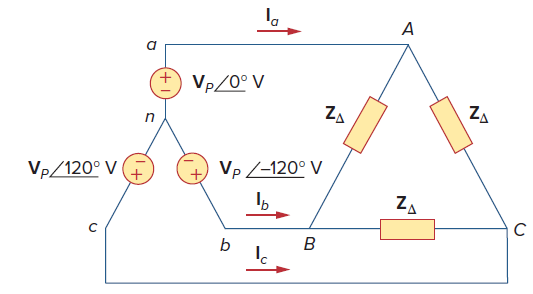
UsingFig. 12.45, design a problem to help other students better understand wye-delta connected circuits.Solve for the line currents in the Y-Δ circuit of Fig. 12.45. Take ZΔ = 60ˆ 45°Î©. + VP/0° V ZA ZA VP /-120° V Vp/120° V ZA ルン
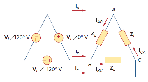
UsingFig. 12.51, design a problem to help other students better understand balanced delta-delta connected circuits.Refer to the Δ-Δ circuit in Fig. 12.51. Find the line and phase currents. Assume that the load impedance is 12 + j9Ω per phase. IAB +, VL/120° V (F
A three-phase generator supplied 10 kVA at a power factor of 0.85 lagging. If 7,500 W are delivered to the load and line losses are 160 W per phase, what are the losses in the generator?
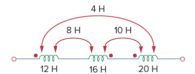
For the three coupled coils inFig. 13.72, calculate the total inductance. 4 H 10 H ele 16 H ell 20 H 12 H
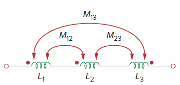
UsingFig. 13.73, design a problem to help other students better understand mutual inductance.Determine the inductance of the three series-connected inductors of Fig. 13.73. Мз M23 M12 ll ll ll Lз
Two coils connected in series-aiding fashion have a total inductance of 500 mH. When connected in a series-opposing configuration, the coils have a total inductance of 300 mH. If the inductance of one coil (L1) is three times the other, find L1, L2, and M. What is the coupling coefficient?
Two coils are mutually coupled, with L1 = 50 mH, L2 = 120 mH, and k = 0.5. Calculate the maximum possible equivalent inductance if:(a) The two coils are connected in series.(b) The coils are connected in parallel.
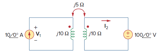
Given the circuit shown inFig. 13.75, determine the value of V1and I2. J5Ω 12 10/0° A (4) V, J10 Ω J10 Ω +) 100/0° V
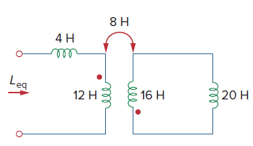
Determine the equivalent Leq in the circuit ofFig. 13.81. 4 H ell eq 12 H 16 H 20 H ele ll
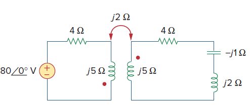
For the circuit inFig. 13.82, determine the impedance seen by the source. j2 N -j1Ω 80/0° V (+ J5 Ω j5 Q j2 Q ell ell
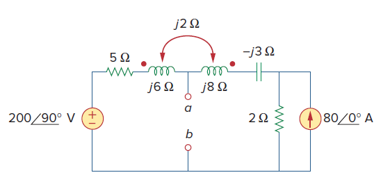
Obtain the Thevenin equivalent circuit for the circuit inFig. 13.83 at terminals a-b. j2 Q -j3 2 J6 Ω J8Ω 200/90° V (+ 2Ω )80/0° A
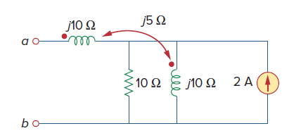
Find the Norton equivalent for the circuit inFig. 13.84 at terminals a-b. J5Ω J10Ω μW wη 2 A (4) 10 Ω 10 Ω
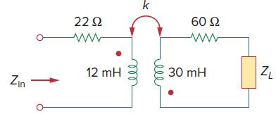
In the circuit ofFig. 13.86, ZLis a 15-mH inductor having an impedance of j40 Ω. Determine Zinwhen k = 0.6. k 22 Q 60 Q 30 mH 12 mH Zin ell
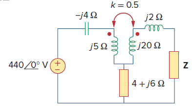
Find the Thevenin equivalent to the left of the load Z in the circuit ofFig. 13.87. k = 0.5 -j4 2 j2 N ell Ej20 2 j5 Q 440/0° V (+ 4 +j6 Q
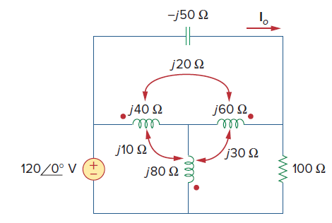
Find current Ioin the circuit ofFig. 13.91. J50 Ω J20 Ω ./40 Ω J60 Ω. η τυ" j10 Ω j30 Ω 120/0° V (+ J80 Ω : 100 Ω υ"
A 240∕2,400-V rms step-up ideal transformer delivers 50 kW to a resistive load. Calculate:(a) The turns ratio.(b) The primary current.(c) The secondary current.
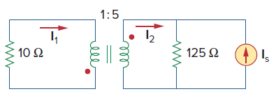
Given I2= 2 A, determine the value of Is inFig. 13.106. 1:5 10 Ω 125 2
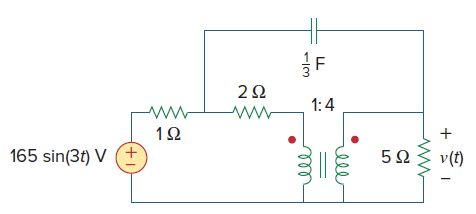
Find v(t) for the circuit inFig. 13.112. 2Ω 1:4 165 sin(3t) V (+ 5Ω v(t) ell
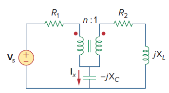
UsingFig. 13.113, design a problem to help other students better understand how ideal transformers work.Find Ix in the ideal transformer circuit of Fig. 13.112. R2 R1 n:1 jXL Vs +1
An autotransformer with a 40 percent tap is supplied by an 880-V, 60-Hz source and is used for stepdown operation. A 5-kVA load operating at unity power factor is connected to the secondary terminals. Find:(a) The secondary voltage,(b) The secondary current,(c) The primary current.
A radio receiver has an input resistance of 300 Ω. When it is connected directly to an antenna system with a characteristic impedance of 75 Ω, an impedance mismatch occurs. By inserting an impedance-matching transformer ahead of the receiver, maximum power can be realized. Calculate the required
Some modern power transmission systems now have major high-voltage DC transmission segments. There are a lot of good reasons for doing this but we will not go into them here. To go from the AC to DC, power electronics are used. We start with three-phase AC and then rectify it (using a full-wave
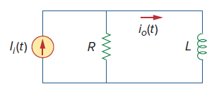
Find the transfer function Ioˆ•Iiof the RL circuit inFig. 14.68. Express it using ω0= Rˆ•L. 1,(t) 1,(t) ele
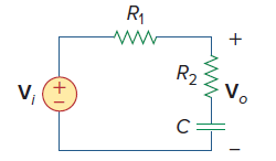
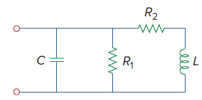
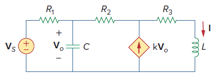
UsingFig. 14.69, design a problem to help other students better understand how to determine transfer functions.Obtain the transfer function Vo/Vi of the circuit in Fig. 14.66. R1 R2 Vo V, (+1
Find G(s) given that g(t) = 2r(t) – 2r(t − 2).
If g(t) = 4e−2t cos 4t, find G(s).
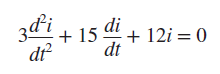
The differential equation that describes the voltage in an RLC network isGiven that v(0) = 0, dv(0)/dt = 6 mAˆ•s, obtain i(t). zdi 38; 15 di + 12i = 0 dt dt²
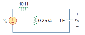
For the circuit shown inFig. 14.70, find H(s) = Vo(s)/Ii(s). 10 H ell 10 Ω νο I; (4) 20 2: 20 H8 rell
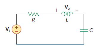
Find the transfer function H(s) = Voˆ•Viof the circuit shown inFig. 14.71. V. ll V, (+)
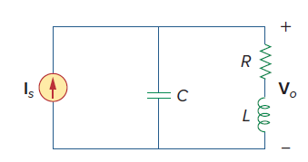
For the circuit shown inFig. 14.72, find H(s) = Voˆ•Is. Vo Is mel
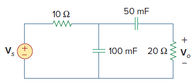
For the circuit shown inFig. 14.73, find H(s) = Vo(s)ˆ•Vs(s). 50 mF 10 Ω 20 2{ 100 mF Vs + >1
Calculate ∣H(ω)∣ if HdB equals(a) 0.1 dB(b) −5 dB(c) 215 dB
Design a problem to help other students calculate the magnitude in dB and phase in degrees of a variety of transfer functions at a single value of ω.Determine the magnitude (in dB) and the phase (in degrees) of H(ω) at ω = 1 if H(ω) equals(a) 0.05(b) 125(c) 10 jω/2 + jω(d) 3/1 + jω + 6/2 +
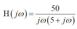
Design a problem to help other students better understand how to determine the Bode magnitude and phase plots of a given transfer function in terms of jω.Sketch the Bode magnitude and phase plots of: 50 H(jø)= jo(5+ j@)
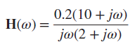
Sketch the Bode plots for 0.2(10 + j@) ja(2 + ja) H(@) =
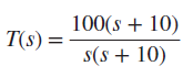
A transfer function is given bySketch the magnitude and phase Bode plots. 100(s + 10) T(s) = s(s + 10)
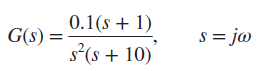
Construct the Bode plots for 0.1(s + 1) G(s) = s = jo S : s*(s + 10)
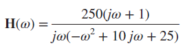
Draw the Bode plots for 250(jo + 1) jo(-a + 10 ja + 25) Но) -
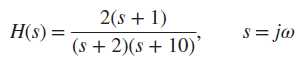
Construct the Bode magnitude and phase plots for 2(s + 1) H(s) = s = ja (s + 2)(s + 10)*
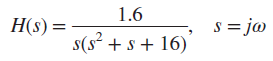
Sketch Bode magnitude and phase plots for 1.6 s = jo H(s) = s(s² + s + 16)
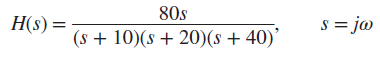
Sketch the asymptotic Bode plots of the magnitude and phase for H(s) = (s + 10)(s + 20)(s + 40)’ 80s s = ja
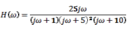
Design a more complex problem than given in Prob. 14.10, to help other students better understand how to determine the Bode magnitude and phase plots of a given transfer function in terms of jω. Include at least a second order repeated root.Sketch the magnitude phase Bode plot for the
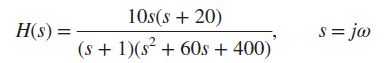
Sketch the magnitude Bode plot for 10s(s + 20) s = ja H(s) = (s + 1)(s² + 60s + 400)
Find the transfer function H(ω) with the Bode magnitude plot shown inFig. 14.74. H (dB) · -20 dB/decade 20 -20 @ (rad/s) 2 20 100
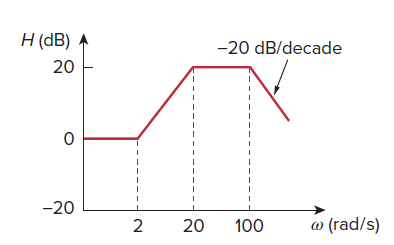
The Bode magnitude plot of H(ω) is shown inFig. 14.75. Find H(ω). H (dB) A 20 0.1 @ (rad/s) 10 +20 dB/decade -40 dB/decade
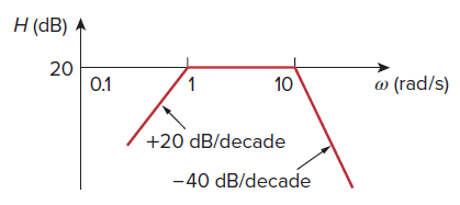
The magnitude plot inFig. 14.76 represents the transfer function of a preamplifier. Find H(s). H (dB) 20 20 dB/decade 2,122 20 dB/decade 50 500
Design a problem to help other students better understand ω0, Q, and B at resonance in series RLC circuits.A coil with resistance 3 Ω and inductance 100 mH is connected in series with a capacitor of 50 pF, a resistor of 6 Ω, and a signal generator that gives 110V-rms at all frequencies.
Design a parallel resonant RLC circuit with ω0 = 100 krad/s and a bandwidth of 10 krad/s. Additionally what is the value of Q?
Design a problem to help other students better understand the quality factor, the resonant frequency, and bandwidth of a parallel RLC circuit.A parallel RLC circuit has the following values:R = 60 Ω, L = 1 mH, and C = 50 μFFind the quality factor, the resonant frequency, and the bandwidth of the
A parallel resonant circuit with a bandwidth of 40 krad/s and the half-power frequencies are ω1 = 4.98 Mrad/s and ω2 = 5.02 Mrad/s, calculate the quality factor and resonant frequency.
A parallel RLC circuit has R = 100 kΩ, L = 100 mH, and a C = 10 μF. Determine the value of Q, the resonant frequency, and the bandwidth. If R = 200 kΩ, how does that affect the values of Q, resonant frequency, and the bandwidth?
A parallel RLC circuit has R = 10 kΩ, L = 100 mH, and a resonant frequency of 200 krad/s. Calculate the value of C, the value of the quality factor, and the bandwidth.
It is expected that a parallel RLC resonant circuit has a midband admittance of 25 × 10−3 S, quality factor of 120, and a resonant frequency of 200 krad/s. Calculate the values of R, L, and C. Find the bandwidth and the half-power frequencies.
Find the resonant frequency of the circuit in Fig. 14.78. ll
A parallel resonance circuit has a resistance of 2 kΩ and half-power frequencies of 86 kHz and 90 kHz. Determine:(a) The capacitance(b) The inductance(c) The resonant frequency(d) The bandwidth(e) The quality factor.
UsingFig. 14.80, design a problem to help other students better understand the quality factor, the resonant frequency, and bandwidth of RLC circuits.For the circuits in Fig. 14.80, find the resonant frequency ω0, the quality factor Q, and the bandwidth B. Let C = 0.1 F, R1 = 10
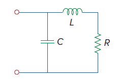
Find the transfer function Voˆ•Vsof the circuit inFig. 14.86. Show that the circuit is a low-pass filter. 10 H 1F= vo € 0.25 2 Vs
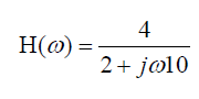
Design a problem to help other students better understand low-pass filters described by transfer functions.Determine the cutoff frequency of the lowpass filter described byFind the gain in dB and phase of H(ω) at ω = 2 rad/s. 4 Н(о) — 2+ jøl0
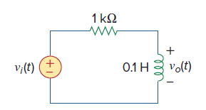
Determine what type of filter is inFig. 14.87. Calculate the corner frequency fc. 1 kQ 0.1 H volt) v;(t) ell
Design a problem to help other students better understand passive high-pass filters.In a highpass RL filter with a cutoff frequency of 100 kHz, L = 40 mH. Find R.
Obtain the transfer function of a high-pass filter with a passband gain of 100 and a cutoff frequency of 40 rad/s.
UsingFig. 14.103, design a problem to help other students better understand how to use PSpice to obtain the frequency response (magnitude and phase of I) in electrical circuits.Use PSpice to provide the frequency response (magnitude and phase of i) of the circuit in Fig. 14.103. Use linear
In a certain application, a simple RC low-pass filter is designed to reduce high frequency noise. If the desired corner frequency is 20 kHz and C = 0.5 μF, find the value of R.
In an amplifier circuit, a simple RC high-pass filter is needed to block the dc component while passing the time-varying component. If the desired roll-off frequency is 15 Hz and C = 10 μF, find the value of R.
Determine the Laplace transform of 3.5 cos (5t − 45°).
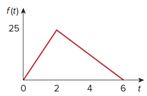
Find the Laplace transform of the signal inFig. 15.26. f(t) A 25 2 4
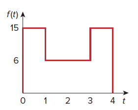
Obtain the Laplace transform of f (t) inFig. 15.28. f(t) A 15 1 2 3 4 t
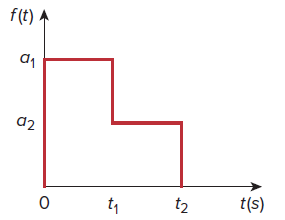
UsingFig. 15.29, design a problem to help other students better understand the Laplace transform of a simple, non-periodic waveshape.Find the Laplace transform of f(t) shown in Fig. 15.29. f(t) A d2 t(s) t2 t1
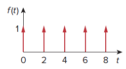
Calculate the Laplace transform of the infinite train of unit impulses inFig. 15.31. f(t) A 8 t 4
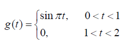
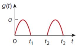
Using Fig. 15.32, design a problem to help other students better understand the Laplace transform of a simple, periodic waveshape.The periodic function shown in Fig. 15.32 is defined over its period asFind G(s). (sin at, g(t) = 0
Apply phasor analysis to evaluate the following:(a) V = [110 sin(20t + 30°) + 220 cos(20t − 90°)] V(b) I = [30 cos(5t + 60°) − 20 sin(5t + 60°)] A
Express the following functions in cosine form:(a) 10 sin(ωt + 30°)(b) −9 sin (8t)(c) −20 sin(ωt + 45°)
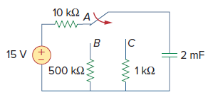
Assuming that the switch inFig. 7.87 has been in position A for a long time and is moved to position B at t = 0, Then at t = 1 second, the switch moves from B to C. Find v C (t) for t ‰¥ 0. 10 ΚΩΑ) B |C 15 V (+ 2 mF 500 ΚΩ: 1 kΩ
An inductive bridge balances when R1 = 1.2 kΩ, R2 = 500 Ω, and Ls = 250 mH. What is the value of Lx, the inductance of the inductor under test?
A capacitance bridge balances when R1 = 100 Ω, R2 = 2 kΩ, and Cs = 40 μF. What is Cx, the capacitance of the capacitor under test?
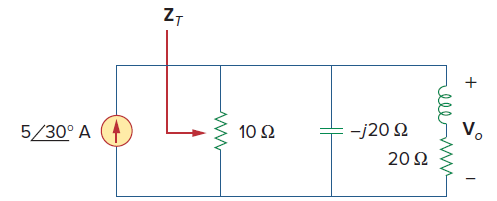
Find ZTand Voin the circuit inFig. 9.71. Let the value of the inductance equal j20 Ω. Z7 V. 10 Ω -j20 2 5/30° A 20 2 elle
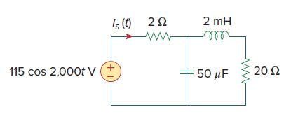
In the circuit ofFig. 9.54, determine the value of is(t). Is (t) 22 ww 2 mH ell 115 cos 2,000t V 20 2 50 µF (+1)
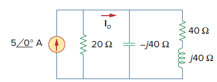
Find current Ioin the circuit shown inFig. 9.50. 40 2 5/0° A -j40 2 20 2 j40 Q relll
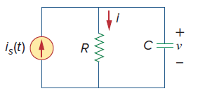
UsingFig. 9.45, design a problem to help other students better understand admittance.Find i(t) and v(t) in each of the circuits of Fig. 9.45.a.b. İç(t) R2 R1 Vs(t) (+ all
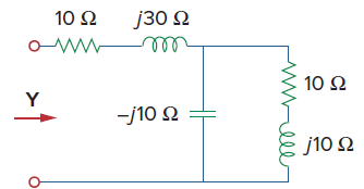
Determine the admittance Y for the circuit inFig. 9.44. 10 Ω J30 Ω σν ο WW 10 Ω Υ -10Ω J10 Ω rell
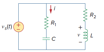
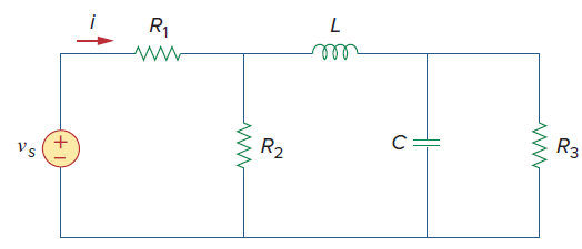
UsingFig. 9.43, design a problem to help other students better understand impedance.In the circuit in Fig. 9.43, determine i. Let vs = 60 cos(200t - 10°) V. R1 R3 R2 Vs (+1
A series RL circuit is connected to a 220-V ac source. If the voltage across the resistor is 170 V, find the voltage across the inductor.
Showing 100 - 200
of 443
1
2
3
4
5
Step by Step Answers