New Semester
Started
Get
50% OFF
Study Help!
--h --m --s
Claim Now
Question Answers
Textbooks
Find textbooks, questions and answers
Oops, something went wrong!
Change your search query and then try again
S
Books
FREE
Study Help
Expert Questions
Accounting
General Management
Mathematics
Finance
Organizational Behaviour
Law
Physics
Operating System
Management Leadership
Sociology
Programming
Marketing
Database
Computer Network
Economics
Textbooks Solutions
Accounting
Managerial Accounting
Management Leadership
Cost Accounting
Statistics
Business Law
Corporate Finance
Finance
Economics
Auditing
Tutors
Online Tutors
Find a Tutor
Hire a Tutor
Become a Tutor
AI Tutor
AI Study Planner
NEW
Sell Books
Search
Search
Sign In
Register
study help
sciences
fundamentals electric circuits
Fundamentals of Electric Circuits 6th edition Charles K Alexander, Matthew Sadiku - Solutions
The open-loop gain of an op amp is 50,000. Calculate the output voltage when there are inputs of +10 μV on the inverting terminal and +20 μV on the noninverting terminal.
Determine the voltage input to the inverting terminal of an op amp when −40 μV is applied to the noninverting terminal and the output through an openloop gain of 150,000 is 15 V.
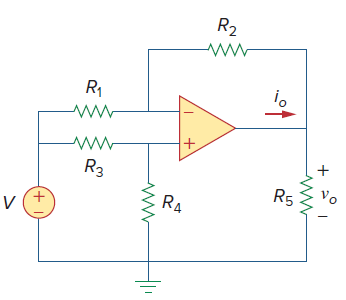
UsingFig. 5.50, design a problem to help other students better understand how ideal op amps work. R2 R1 vo R3 R5 RA (+1
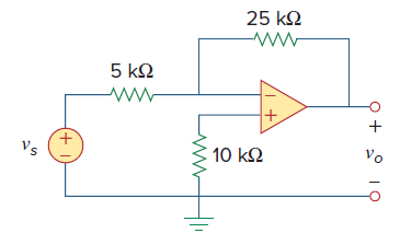
Calculate the voltage ratio voˆ•vsfor the op amp circuit ofFig. 5.51. Assume that the op amp is ideal. 25 k2 5 kN Vo Vs 10 k2 + 1)
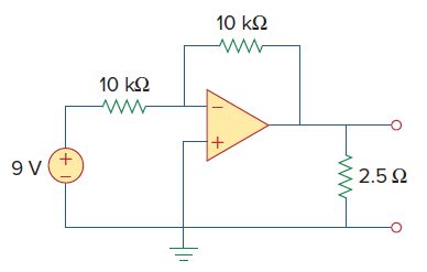
For the circuit shown inFigure 5.57, solve for the Thevenin equivalent circuit looking into terminals A and B. 10 k2 10 k2 +, +, 2.5 2
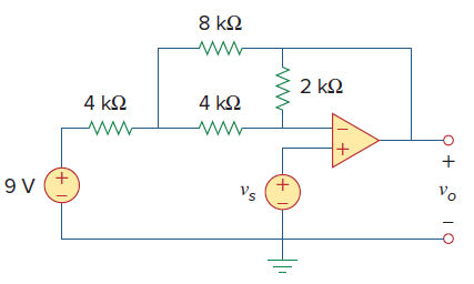
In the circuit ofFig. 5.59, calculate voof vs= 2 V. 8 k2 2 k2 4 k2 4 k2 Vo Vs (+I) + I
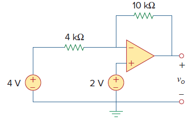
Calculate voin the op amp circuit ofFig. 5.60. 10 k2 4 kN Vo 2 V 4 V (+ (+)
Design an inverting amplifier with a gain of −15.
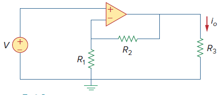
UsingFig. 5.64, design a problem to help other students better understand noninverting op amps.Determine io in the circuit of Fig. 5.64. H'o R3 R2 R, (+I)
Design a noninverting amplifier with a gain of 7.5.
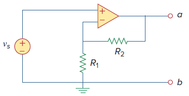
For the circuit shown inFig. 5.73, find the Thevenin equivalent at terminals a-b. R2 Vs R1 + 1)
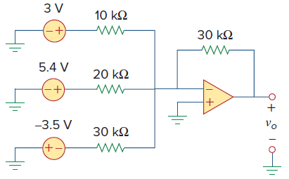
Determine the output of the summing amplifier in Fig. 5.74. 3 V 10 k2 30 kQ 5.4 V 20 k2 -3.5 V Vo 30 k2 +-) to
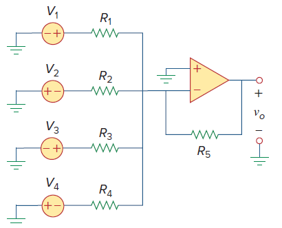
UsingFig. 5.75, design a problem to help other students better understand summing amplifiers.Calculate the output voltage due to the summing amplifier shown in Fig. 5.75. V, R1 V2 R2 (+-) Vo V3 R3 R5 VA R4
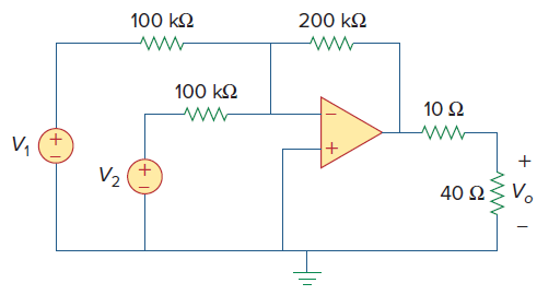
Referring to the circuit shown inFig. 5.77, determine Voin terms of V1and V2. 200 k2 100 k2 100 kQ 10 Ω V, V2 Vo 40 2
The feedback resistor of a three-input averaging summing amplifier is 50 kΩ. What are the values of R1, R2, and R3?
The feedback resistor of a five-input averaging summing amplifier is 40 kΩ. What are the values of R1, R2, R3, R4, and R5?
Design a difference amplifier to have a gain of 4 and a common-mode input resistance of 20 kΩ at each input.
Design a circuit to amplify the difference between two inputs by 2.5.(a) Use only one op amp.(b) Use two op amps.
Design an op amp circuit such thatvo = 4v1 + 6v2 − 3v3 − 5v4Let all the resistors be in the range of 20 to 200 kΩ.
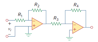
UsingFig. 5.83, design a problem to help other students better understand cascaded op amps.Calculate the gain of the op amp circuit shown in Fig. 5.83. R2 R4 R1 R3 ww Vi
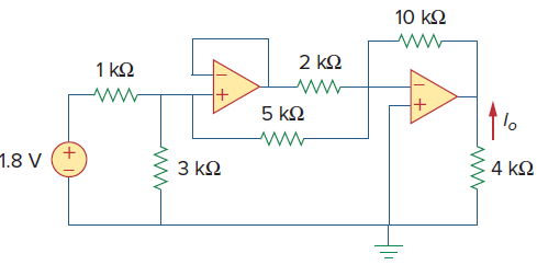
Calculate ioin the op amp circuit ofFig. 5.85. 10 k2 2 kQ 1 k2 5 kQ 1.8 V 3 ΚΩ 4 k2
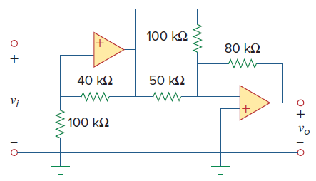
Calculate voˆ•viin the op amp circuit ofFig. 5.87. 100 k2 80 k2 40 k2 50 k2 Vi 100 k2 Vo
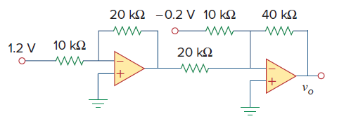
Determine voin the circuit ofFig. 5.88. 20 k2 -0.2 V 10 k2 40 k2 1.2 V 10 k2 20 k2
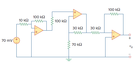
Find vo in the op amp circuit ofFig. 5.92. 100 k2 www 100 k2 10 k2 100 k2 30 к2 30 k2 +. ww- 70 mv 70 kQ Vo Q+
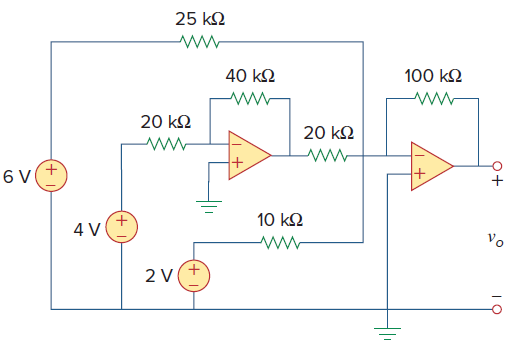
For the circuit inFig. 5.93, find vo. 25 k2 100 k2 40 k2 20 k2 20 k2 10 k2 Vo +, 2 V 0+
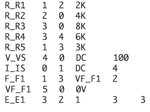
If the Schematics Netlist for a network is as follows, draw the network. 1 2 2K 2 0 4K 3 0 8K R_R1 R_R2 R_R3 3 4 6K 1 3 ЗК 4 0 DC 0 1 DC 1 3 VF F1 2 R_R4 R_R5 V_VS I_IS 100 4 F_F1 VF_F1 2 1 E_E1 3 3.
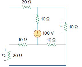
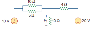
Determine v1and v2in the circuit ofFig. 3.101. 20 Ω 10Ω 10 Ω 100 V 10 Ω 10 Ω 20 Ω
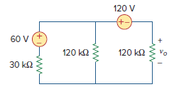
Obtain vain the circuit ofFig. 3.54. 120 V +- 60 V 120 k2 120 k2 Vo 30 k2
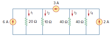
Given the circuit inFig. 3.53, calculate the currents i1through i4. ЗА i3 μ 40 Ω 10Ω 40 Ωξ 20Ω
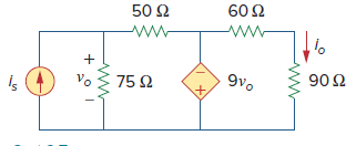
Calculate the current gain ioˆ•isin the circuit ofFig. 3.105. 60 Ω 50 Ω 90Ω 9νο νο 75 Ω
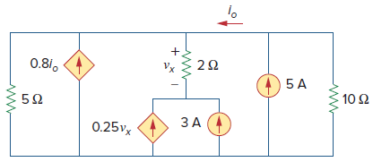
Find vxand ixin the circuit shown inFig. 3.107. 0.81, Vx 10Ω ЗА 0.25vx
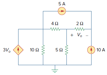
Obtain the node-voltage equations for the circuit inFig. 3.111 by inspection. Then solve for Vo. 5 A + V. 3V. 10 A 10 Ω
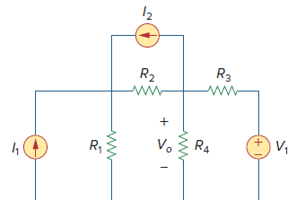
UsingFig. 3.112, design a problem, to solve for Vo, to help other students better understand nodal analysis. Try your best to come up with values to make the calculations easier.Find the voltage Vo in the circuit of Fig. 3.112. R3 R2 ww- ww- +. V, Vo R4 R1 (+i
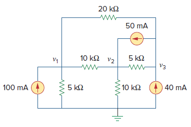
For the circuit shown inFig. 3.113, write the nodevoltage equations by inspection. 20 k2 50 mA 10 k2 v2 5 k2 V3 10 k2 40 mA 100 mA 5 k2
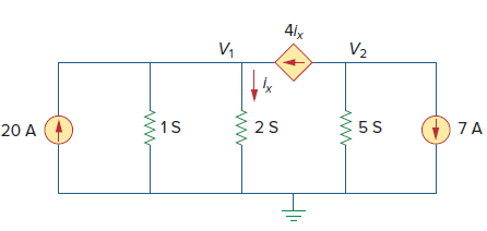
Write the node-voltage equations by inspection and then determine values of V1and V2in the circuit ofFig. 3.114. 41x V2 V, 7A 5S 1S 2 S 20 A
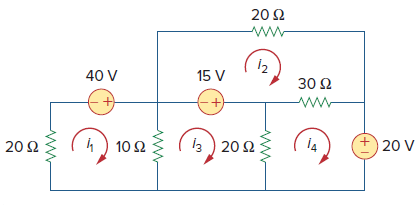
By inspection, write the mesh-current equations for the circuit inFig. 3.116. 20Ω www 40 V 15 ν 30 Ω b) 20Ω +, 14 20 V 20Ω 10Ω
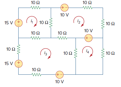
Write the mesh-current equations for the circuit in Fig. 3.117. 10Ω 10 Ω 10 V 1) 10Ω 15 V (+ 10 Ω 10 V 10Ω 10 Ω (+ 10 Ω İ4 10 Ω 10Ω 15 V (+ 10 Ω +) 10 V
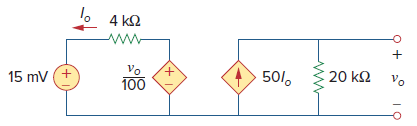
Calculate voand Ioin the circuit ofFig. 3.121. 4 k2 15 mv (+ 20 k2 Vo Vo +. 50/, 100
An audio amplifier with a resistance of 9 Ω supplies power to a speaker. What should be the resistance of the speaker for maximum power to be delivered?
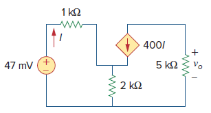
For the simplified transistor circuit ofFig. 3.122, calculate the voltage vo. 1 k2 www 400/ vo 5 k2 47 mV 2 k2
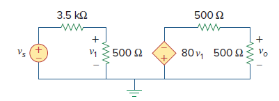
For the circuit inFig. 3.123, find the gain voˆ•vs. 3.5 k2 500 2 ww- Vo 80 v, 500 2 Vs 500 2
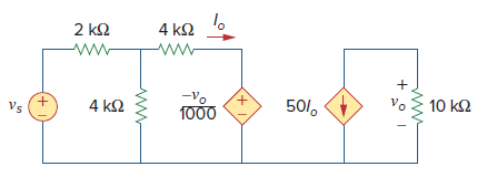
Determine the gain voˆ•vsof the transistor amplifier circuit inFig. 3.124. 4 k2 2 k2 vo 10 k2 -Vo +, 1000 50/, Vs +. 4 k2
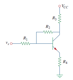
UsingFig. 3.128, design a problem to help other students better understand transistors. Make sure you use reasonable numbers!Given the circuit shown in Fig. 3.28 and R1 = 100 kΩ, R2 = 1 kΩ, R3 = 1 kΩ, R4 = 100 Ω, β = 100, VCC = 30 V,
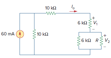
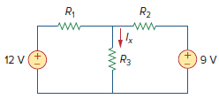
In the circuit ofFig. 3.102, find the values of R, V1, and V2given that io= 15 mA. 10 k2 6 k23 V, 60 mA (4 10 k2 +* 6 k2 R V2
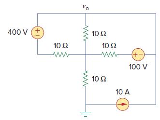
Apply mesh analysis to find voin the circuit ofFig. 3.96. νο 400 V 10Ω 10Ω 10Ω +) 100 V 10 Ω 10 A +1
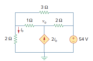
Find voand ioin the circuit ofFig. 3.94. Vo +) 54 V 21.
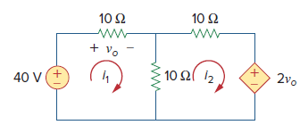
Calculate the mesh currents i1and i2inFig. 3.92. 10 Ω ww 10Ω www +νο 10 Ω 2νο 40 V
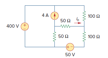
Use mesh analysis to obtain io in the circuit ofFig. 3.90. 4 A 100 Ω 50 Ω 400 V 50 Ω 100 Ω 50 V +)
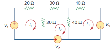
Using Figure 3.88 design a problem to help students better understand mesh analysis using matrices. 10 Ω 30 Ω 20Ω 40 Ω 30 Ω V3 ν. 12 +) ν.
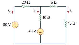
Use mesh analysis to obtain ia, ib, and icin the circuit inFig. 3.84. 5Ω 20Ω la 10 Ω : 15 Ω 30 V(+ 45 V
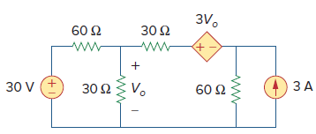
Use nodal analysis to find Voin the circuit ofFig. 3.72. 3Vο 30 Ω 60 Ω ЗА 30 Ω ν. 30 V 60 Ω +1
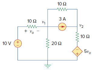
Determine v1and v2in the circuit ofFig. 3.71. 10 Ω ЗА 10 Ω V1 V2 + v. 10Ω 20Ω 10 V (+ 5νο
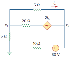
For the circuit inFig. 3.70, find v1and v2using nodal analysis. 21. 20 Ω V2 ww 10Ω 30 V
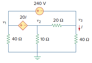
For the circuit inFig. 3.69, find v1, v2, and v3using nodal analysis. 240 V (+- 201 V3 20 Ω V2 ν1 40 Ω 40 Ω 10 Ω
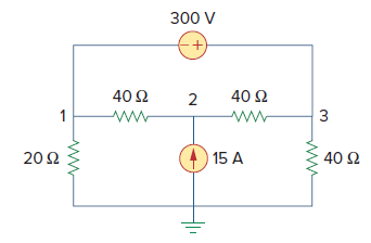
Determine the node voltages in the circuit inFig. 3.67 using nodal analysis. 300 V 40 Ω 40 Ω 1 20Ω 15 A 40 Ω 2.
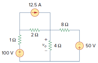
Apply nodal analysis to find ioand the power dissipated in each resistor in the circuit ofFig. 3.64. 12.5 A 50 V Vo 100 V (+
Using nodal analysis, find voin the circuit ofFig. 3.63. 12.5 A 50 V Vo 100 V (+
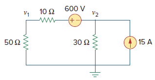
Calculate v1and v2in the circuit ofFig. 3.62 using nodal analysis. 600 V V2 10 Ω νi +) 50 Ω (4) 15 A 30 Ω
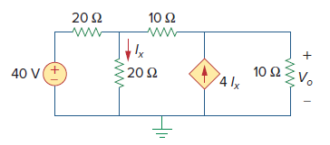
Using nodal analysis, determine Voin the circuit inFig. 3.61. 10 Ω 20 Ω 10 Ω: 4 Ix ν. : νο 20Ω 40 V
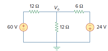
Find Voand the power dissipated in all the resistors in the circuit ofFig. 3.60. 12Ω 6Ω Vo 60 V (+ 12Ω 24 V (1+
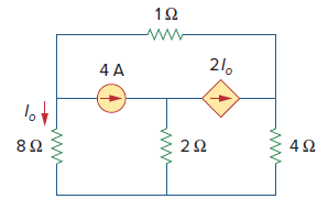
Find lothe circuit ofFig. 3.59. 1Ω 21. 4 A lov 4Ω 2Ω 8Ω
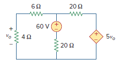
Using nodal analysis, find voin the circuit ofFig. 3.57. 202 62 ww- 60 V 5vo vo 20 2 +1)
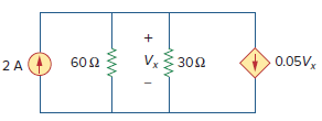
Apply nodal analysis to solve for Vxin the circuit ofFig. 3.56. V 302 0.05V, 2 A 60 2
Solve for V1in the circuit ofFig. 3.55 using nodal analysis. 10 2 20 V 10 V V, 102 +,
UsingFig. 3.50, design a problem to help other students better understand nodal analysis. R2 12 V
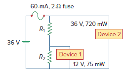
Two delicate devices are rated as shown inFig. 2.142. Find the values of the resistors R1and R2needed to power the devices using a 36-V battery. 60-mA, 2-2 fuse 36 V, 720 mW R1 Device 2 36 V+ Device 1 R2 12 V, 75 mW
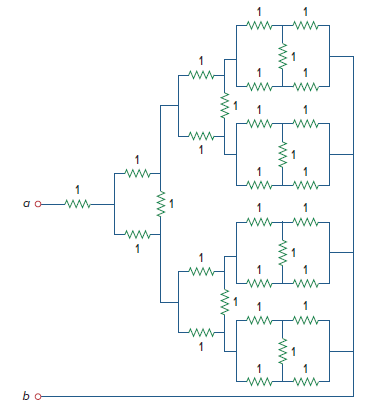
Repeat Prob. 2.75 for the eight-way divider shown inFig. 2.136.Prob 2.75Find Rab in the four-way power divider circuit in Fig. 2.135. Assume each R = 4 Ω. inIim LinLw Lui bo ww- ww- ER ER R. :R
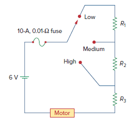
The circuit inFig. 2.134 is to control the speed of a motor such that the motor draws currents 5 A, 3 A, and 1 A when the switch is at high, medium, and low positions, respectively. The motor can be modeled as a load resistance of 20 mΩ. Determine the series dropping resistances
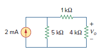
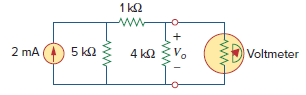
(a) Obtain the voltage Voin the circuit ofFig. 2.127(a).(b) Determine the voltage Vʹo measured when a voltmeter with 6-kΩ internal resistance is connected as shown in Fig. 2.127(b).(c) The finite resistance of the meter introduces an error into the measurement. Calculate the
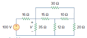
Determine V in the circuit ofFig. 2.120. 30 2 ww- 16 2 10 Ω 15 2 20 Ω 100 V 35 2 12 2 +.
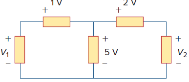
In the circuit ofFig. 2.75, calculate V1and V2. V2 5 V V,
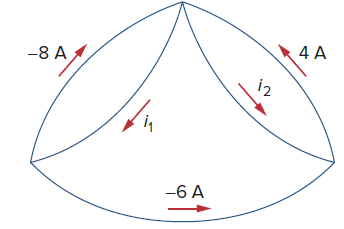
Determine i1and i2in the circuit ofFig. 2.74. 4 A -8 A i2 -6 A
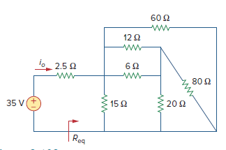
Find Reqand ioin the circuit ofFig. 2.102. 12 2 o 2.50 80 Ω 35 V(+ 15 2 20 2 TRea
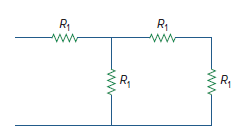
Given the circuit inFig. 2.101 and that the resistance, Req, looking into the circuit from the left is equal to 100 Ω, determine the value of R1. R ww R1 R,
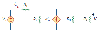
For the circuit inFig. 2.88, find Vo/ Vsin terms of α, R1, R2, R3, and R4. If R1= R2= R3= R4, what value of α will produce |Vo/ Vs| = 10? R2 al. R3 V. RA V.
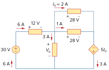
Find Voand the power absorbed by each element in the circuit ofFig. 1.31. 1o= 2 A 28 V 12 V 1A ЗА 28 V 5/o V. 30 V 1ЗА 6A4 +1
A 150-W incandescent outdoor lamp is connected to a 120-V source and is left burning continuously for an average of 12 hours per day. Determine:(a) The current through the lamp when it is lit.(b) The cost of operating the light for one non-leap year if electricity costs 9.5 cents per kWh.
Design a problem, complete with a solution, to help students to better understand Ohm’s law. Use at least two resistors and one voltage source.The voltage across a 5-kΩ resistor is 16 V. Find the current through the resistor.
Find the hot resistance of a light bulb rated 60 W, 120 V.
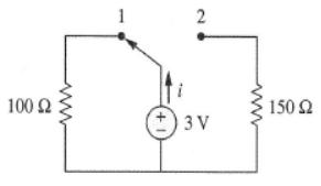
(a) Calculate current i in Fig. 2.68 when the switch is in position 1.(b) Find the current when the switch is in position 2. 1 100 Ω 150 Ω 3ν 2.
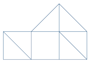
For the network graph inFig. 2.69, find the number of nodes, branches, and loops.
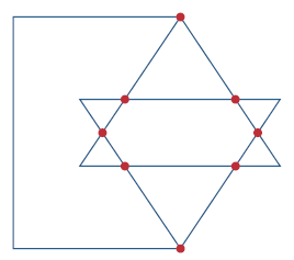
In the network graph shown inFig. 2.70, determine the number of branches and nodes.
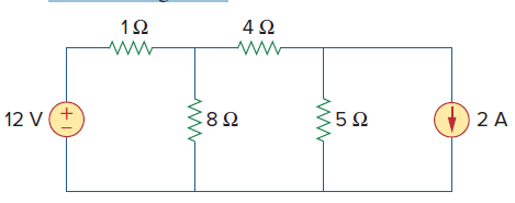
Determine the number of branches and nodes in the circuit ofFig. 2.71. 1Ω 4Ω 352 12 V 2 A
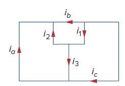
Design a problem, complete with a solution, to help other students better understand Kirchhoff€™s Current Law. Design the problem by specifying values of ia, ib, and ic, shown inFig. 2.72, and asking them to solve for values of i1, i2, and i3. Be careful to specify realistic currents.Use
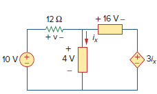
Calculate v and ixin the circuit ofFig. 2.79. + 16 V- 12 2 ww +v- 3ix 4 V 10 V (+1)
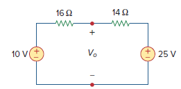
Determine Voin the circuit inFig. 2.80. 14 2 16 2 25 V Vo 10 V +,
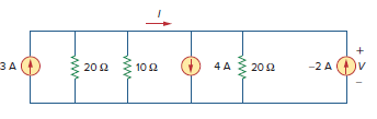
Find I and V in the circuit ofFig. 2.82. 4 A 202 -2 A 10 2 20 2 3A
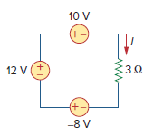
From the circuit inFig. 2.83, find I, the power dissipated by the resistor, and the power supplied by each source. 10 V +. 12 V +. -8 V (+1)
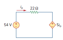
Determine io in the circuit ofFig. 2.84. 222 51o 54 V(+
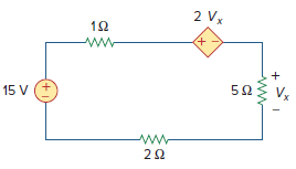
Find Vxin the circuit ofFig. 2.85. 2 Vx +, ww- 15 V
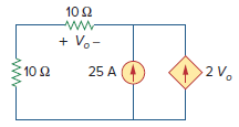
Find Voin the circuit in Fig. 2.86 and the power absorbed by the dependent source. 10 2 + V.- 2 V. 25 A 10 2
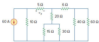
In the circuit shown inFig. 2.87, determine Vxand the power absorbed by the 60-Ω resistor. 62 20 2 40 Ω 60 A 10Ω 60 Ω 15 2 302
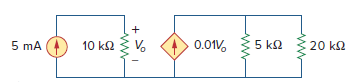
For the network inFig. 2.89, find the current, voltage, and power associated with the 20-kΩ resistor. 5 mA 10 k2 0.01V. V. 5 k2 20 k2
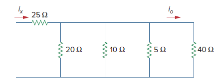
For the circuit inFig. 2.90, io= 3 A. Calculate ixand the total power absorbed by the entire circuit. 1ο 25Ω 40 Ω -5Ω 10 Ω 20Ω
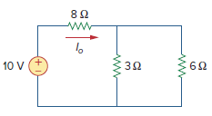
Calculate Ioin the circuit ofFig. 2.91. 82 10 V (+1)
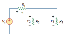
Design a problem, usingFig. 2.92, to help other students better understand series and parallel circuits.Find v1, v2, and v3 in the circuit in Fig. 2.92. + v1 - R3 v3 R2 v2
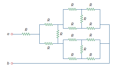
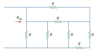
All resistors (R) inFig. 2.93 are 10 Ω each. Find Req. R Reg R.
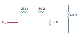
Find Reqfor the circuit inFig. 2.94. 180 2 25 2 :60 2 60 2 Rea
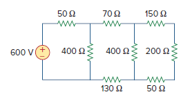
Using series/parallel resistance combination, find the equivalent resistance seen by the source in the circuit ofFig. 2.98. Find the overall absorbed power by the resistor network. 70 2 50 2 150 2 200 2 400 2 400 2 600 V 50 2 130 2
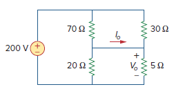
Calculate Voand Ioin the circuit ofFig. 2.99. 30 Ω 70 Ω 200 V 20 Ω 5Ω
Showing 300 - 400
of 443
1
2
3
4
5
Step by Step Answers