New Semester
Started
Get
50% OFF
Study Help!
--h --m --s
Claim Now
Question Answers
Textbooks
Find textbooks, questions and answers
Oops, something went wrong!
Change your search query and then try again
S
Books
FREE
Study Help
Expert Questions
Accounting
General Management
Mathematics
Finance
Organizational Behaviour
Law
Physics
Operating System
Management Leadership
Sociology
Programming
Marketing
Database
Computer Network
Economics
Textbooks Solutions
Accounting
Managerial Accounting
Management Leadership
Cost Accounting
Statistics
Business Law
Corporate Finance
Finance
Economics
Auditing
Tutors
Online Tutors
Find a Tutor
Hire a Tutor
Become a Tutor
AI Tutor
AI Study Planner
NEW
Sell Books
Search
Search
Sign In
Register
study help
sciences
fundamentals electric circuits
Fundamentals of Electric Circuits 6th edition Charles K Alexander, Matthew Sadiku - Solutions
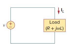
UsingFig. 9.40, design a problem to help other students better understand phasor relationships for circuit elements.Two elements are connected in series as shown in Fig. 9.40.If i = 12 cos (2t - 30°) A, find the element values. Load (R + j@L)
A series RLC circuit has R = 80 Ω, L = 240 mH, and C = 5 mF. If the input voltage is v(t) = 115 cos 2t, find the current flowing through the circuit.
Determine the current that flows through an 20-Ω resistor connected to a voltage source vs = 120 cos (377t + 37°) V.
Transform the following sinusoids to phasors:(a) −20 cos(4t + 135°)(b) 8 sin(20t + 30°)(c) 20 cos (2t) + 15 sin (2t)
Given v1 = 45 sin(ωt + 30°) V and v2 = 50 cos(ωt − 30°) V, determine the phase angle between the two sinusoids and which one lags the other.
A current source in a linear circuit has is = 15 cos (25 π t + 25°) A(a) What is the amplitude of the current?(b) What is the angular frequency?(c) Find the frequency of the current.(d) Calculate is at t = 2 ms.
A load is modeled as a 100-mH inductor in parallel with a 12-Ω resistor. A capacitor is needed to be connected to the load so that the network is critically damped at 60 Hz. Calculate the size of the capacitor.
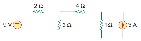
Draw the dual of the circuit shown inFig. 8.118. 4Ω 9 V(+ 6Ω ЗА
Given the circuit shown inFig. 8.103, determine the characteristic equation of the circuit and the values for i(t) and v(t) for all t > 0. i(t) v(t) 12 2 8Ω 2[1- u(t)] A 2 H 18 + ?!
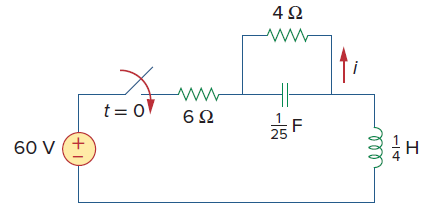
In the circuit ofFig. 8.102, find i(t) for t > 0. 4Ω t = 0 6Ω 60 V (+
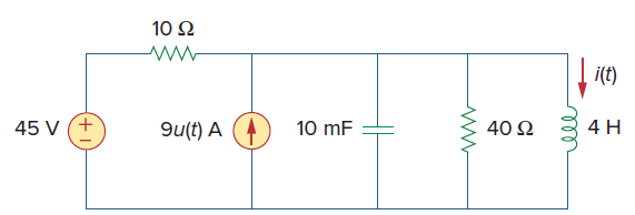
For the circuit inFig. 8.97, find i(t) for t > 0. 10 2 i(E) 40 2 45 V (+ 4 H 9u(t) A 10 mF all
Determine i(t) for t > 0 in the circuit ofFig. 8.96. 5Ω 3[1– u(t)] A +) 45 V 50 mF 5 H i(t) elle
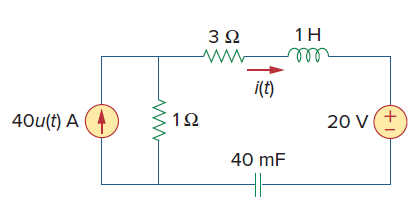
For the network inFig. 8.89, find i(t) for t > 0. 1H 3Ω all i(t) 40u(t) A (4 20 V(+ 40 mF
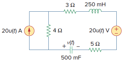
Determine v(t) for t > 0 in the circuit ofFig. 8.87. 250 mH 3Ω 20u(t) V (+ 4Ω 20u(t) A v(t) 500 mF
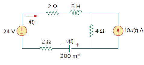
Obtain v(t) and i(t) for t > 0 in the circuit ofFig. 8.84. 2Ω 5H i(t) 10u(t) A 4Ω 24 V v(t) 2Ω 200 mF
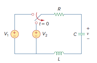
UsingFig. 8.83, design a problem to help other students better understand the step response of series RLC circuits.Determine v(t) for t > 0 in the circuit in Fig. 8.83. Ot= 0 V, V2 C= +1.
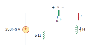
Calculate i(t) for t > 0 in the circuit ofFig. 8.82. + v - 16 35u(-t) V (+ 5Ω
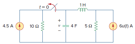
Find v(t) for t > 0 in the circuit ofFig. 8.81. t = 0 1H ll 4.5 A 6u(t) A 5Ω 10 Ω
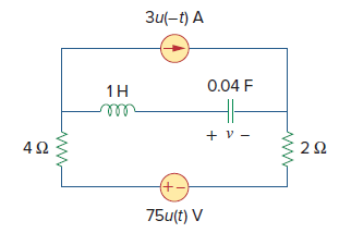
For the circuit inFig. 8.80, find v(t) for t > 0. Зи-t) А 0.04 F 1H elll 4Ω +. 75u(t) V
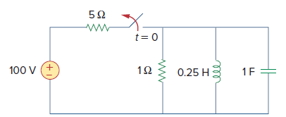
Find the voltage across the capacitor as a function of time for t > 0 for the circuit inFig. 8.72. Assume steady-state conditions exist at t = 0ˆ’. t= 0 100 v (+ 0.25 H 1F ell
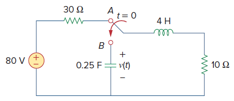
The switch inFig. 8.69 moves from position A to position B at t = 0 (please note that the switch must connect to point B before it breaks the connection at A, a make-before-break switch). Let v(0) = 0, find v(t) for t > 0. 30 Ω 4 H ell 80 V 10 Ω 0.25 F ν ) (+)
If R = 50 Ω, L = 1.5 H, what value of C will make an RLC series circuit:(a) Overdamped,(b) Critically damped,(c) Underdamped?
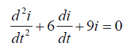
Design a problem to help other students better understand source-free RLC circuits.The branch current in an RLC circuit is described by the differential equationand the initial conditions are i(0) = 0, di(0)/dt = 4. Obtain the characteristic equation and determine i(t) for t > 0. d'i di +6–+9i
A series RLC circuit has R = 20 kΩ, L = 0.2 mH, and C = 5 μF. What type of damping is exhibited by the circuit?
A capacitor with a value of 10 mF has a leakage resistance of 2 MΩ. How long does it take the voltage across the capacitor to decay to 40% of the initial voltage to which the capacitor is charged? Assume that the capacitor is charged and then set aside by itself.
An RC circuit consists of a series connection of a 120-V source, a switch, a 34-MΩ resistor, and a 15-μF capacitor. The circuit is used in estimating the speed of a horse running a 4-km racetrack. The switch closes when the horse begins and opens when the horse crosses the finish line. Assuming
In designing a signal-switching circuit, it was found that a 100-μF capacitor was needed for a time constant of 3 ms. What value resistor is necessary for the circuit?
In the circuit ofFig. 7.144, find the value of iofor all values of 0 < t. 10 Ω 10 Ω 5Ω 1A 10 Ω 25[1 – u(t)] V (+ :50 mF
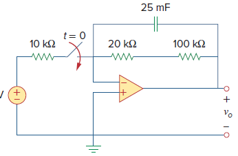
For the op amp circuit inFig. 7.134, find vo(t) for t > 0. 25 mF t= 0 100 k2 10 k2 20 k2 Vo +1
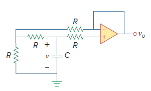
If v(0) = 10 V, find vo(t) for t > 0 in the op amp circuit inFig. 7.132. Let R = 100 kΩ and C = 20 μF. R R + R R C
The voltage across a 10-mH inductor is 45δ(t − 2)mV. Find the inductor current, assuming that the inductor is initially uncharged.
Design a problem to help other students better understand singularity functions.Sketch each of the following waveforms.(a) i(t) = [u(t–2)+u(t+2)] A(b) v(t) = [r(t) – r(t–3) + 4u(t–5) – 8u(t–8)] V
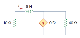
In the circuit ofFig. 7.99, find i(t) for t > 0 if i(0) = 5 A. 10 Ω 0.51 40 Ω
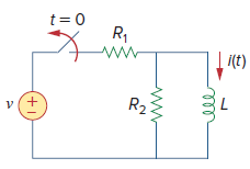
UsingFig. 7.92, design a problem to help other students better understand source-free RL circuits.The switch in the circuit in Fig. 7.90 has been closed for a long time. At t = 0, the switch is opened. Calculate i(t) for t > 0. t = 0 R, ww i(t) R2
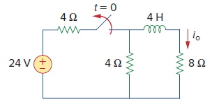
For the circuit inFig. 7.91, find iofor t > 0. t= 0 4 H 24 V(+ 4Ω 8Ω
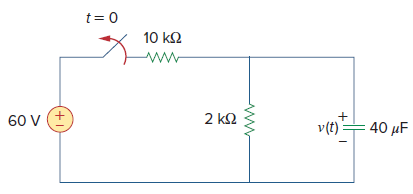
The switch inFig. 7.86 has been closed for a long time, and it opens at t = 0. Find v(t) for t ‰¥ 0. t= 0 10 k2 2 k2 60 V (+ v(t)= 40 µF
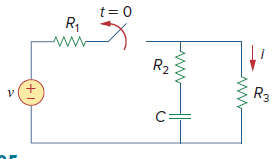
UsingFig. 7.85, design a problem to help other students better understand source-free RC circuits.For the circuit shown in Fig. 7.85, find i(t), t > 0. t= 0 R, R2 R3 +1
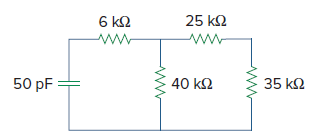
Determine the time constant for the circuit inFig. 7.83. 6 k2 25 k2 50 pF = 40 k2 35 k2
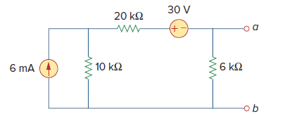
Find the Norton equivalent with respect to terminals a-b in the circuit shown inFig. 4.104. 30 V 20 k2 +) : 10 k오 6 k2 6 mA ob
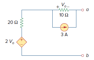
Find the Norton equivalent at terminals a-b of the circuit inFig. 4.119. Vo- +. 10 Ω 20 Ω ЗА 2 V.
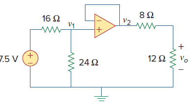
Find voin the op amp circuit ofFig. 5.65. 8Ω v2 16 Ω V1 +, νο 12Ω 7.5 V 24 Ω +)
Design a problem to help other students better understand how capacitors work.In 5 s, the voltage across a 40-mF capacitor changes from 160 V to 220 V. Calculate the average current through the capacitor.
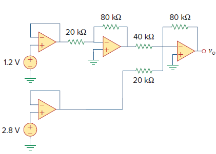
Obtain the output voin the circuit ofFig. 5.94. 80 k2 80 k2 20 k2 40 k2 www ww- 1.2 V 20 k2 +. 2.8 V +,
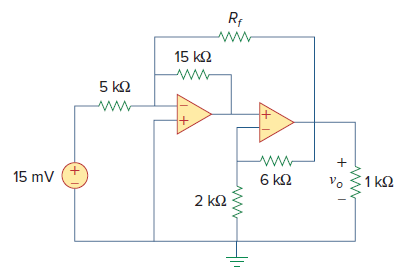
Find voin the circuit ofFig. 5.95, assuming that Rf= ˆž (open circuit). R; 15 k2 5 k2 15 mV 6 k2 1 k2 2 k2 +,
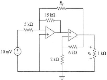
Repeat the previous problem if Rf = 10 kΩ.Previous Problem ww 15 k2 ww 5 kn ww ww- 10 mv (+ 6 k2 I kQ 2 k2
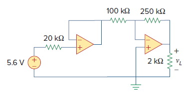
Find the load voltage vLin the circuit ofFig. 5.98. 100 k2 250 kO 20 k2 +. 2 k2 5.6 V
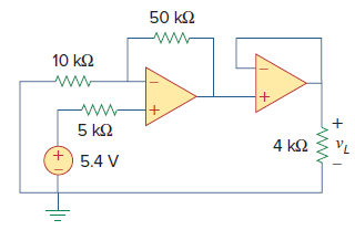
Determine the load voltage vLin the circuit ofFig. 5.99. 50 k2 10 k2 5 k2 4 k2 5.4 V +,
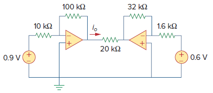
Find ioin the op amp circuit ofFig. 5.100. 100 k2 32 ka 10 k2 1.6 kQ 20 k2 0.9 V(+ 0.6 V +)
A four-bit DAC covers a voltage range of 0 to 10 V. Calculate the resolution of the DAC in volts per discrete binary step.
Design a voltage controlled ideal current source (within the operating limits of the op amp) where the output current is equal to 200 vs(t) μA.
Design a circuit that provides a relationship between output voltage vo and input voltage vs such that vo = 12vs − 10. Two op amps, a 6-V battery, and several resistors are available.
If the voltage across a 7.5-F capacitor is 2te−3t V, find the current and the power.
A 50-μF capacitor has energy w(t) = 10 cos2 377t J. Determine the current through the capacitor.
A voltage across a capacitor is equal to [2 – 2 cos(4t)] V and the current flowing through it is equal to 2 sin (4t) μA. Determine the value of the capacitance. Calculate the power being stored by the capacitor.
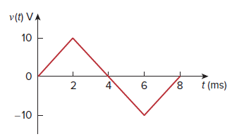
The voltage across a 4-μF capacitor is shown inFig. 6.45. Find the current waveform. v(t) VA 10 2 t (ms) -10 00 4)
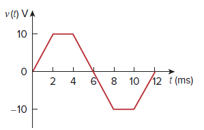
The voltage waveform inFig. 6.46 is applied across a 55-μF capacitor. Draw the current waveform through it. v (t) VA 10 12 t (ms) 6 8 10 2 4 -10
At t = 0, the voltage across a 25-mF capacitor is 10 V. Calculate the voltage across the capacitor for t > 0 when current 5t mA flows through it.
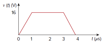
The voltage across a 5-mF capacitor is shown inFig. 6.47. Determine the current through the capacitor. v (t) (V) A 16 t (us) 2 3 4 3.
A voltage of 45e−2000t V appears across a parallel combination of a 100-mF capacitor and a 12-Ω resistor. Calculate the power absorbed by the parallel combination.
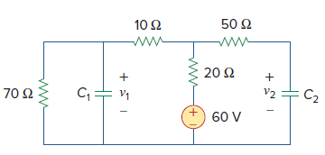
Find the voltage across the capacitors in the circuit ofFig. 6.49 under dc conditions. 50 Ω 10 Ω 20 Ω V2 C2 70 Ω 60 V (+I
Two capacitors (25 and 75 μF) are connected to a 100-V source. Find the energy stored in each capacitor if they are connected in:(a) Parallel(b) Series
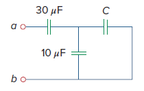
The equivalent capacitance at terminals a-b in the circuit ofFig. 6.50 is 20 μF. Calculate the value of C. 30 иF 10 μF
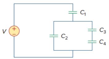
Using Fig. 6.57, design a problem that will help other students better understand how capacitors work together when connected in series and in parallel.For the circuit in Fig. 6.57, determine:(a) The voltage across each capacitor,(b) The energy stored in each capacitor. C3 V C2 C4
Three capacitors, C1 = 5 μF, C2 = 10 μF, and C3 = 20 μF, are connected in parallel across a 200-V source. Determine:(a) The total capacitance,(b) The charge on each capacitor,(c) The total energy stored in the parallel combination.
Given that four 10-μF capacitors can be connected in series and in parallel, find the minimum and maximum values that can be obtained by such series/parallel combinations.
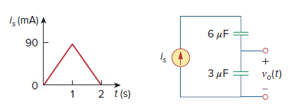
Assuming that the capacitors are initially uncharged, find vo(t) in the circuit ofFig. 6.62. İç (mA) A 6 μF 90 is 3 µF vo(t) 2 t(s)
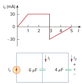
If v(0) = 0, find v(t), i1(t), and i2(t) in the circuit ofFig. 6.63. Is (mA). 30 5 t -30 6 μF is 4μF
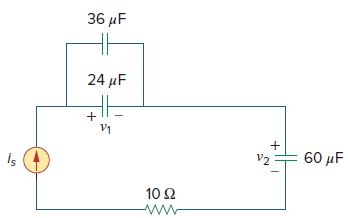
In the circuit inFig. 6.64, let is= 4.5eˆ’2tmA and the voltage across each capacitor is equal to zero at t = 0. Determine v1and v2and the energy stored in each capacitor for all t > 0. 36 μ 24 μ V1 is 60 μ V2 10 Ω Wη
The current through a 25-mH inductor is 10e−t∕2 A. Find the voltage and the power at t = 3 s.
An inductor has a linear change in current from 100 mA to 200 mA in 2 ms and induces a voltage of 160 mV. Calculate the value of the inductor.
Design a problem to help other students better understand how inductors work.The current through a 12-mH inductor is i(t) = 30te-2t. A, t ≥ 0. Determine:(a) The voltage across the inductor,(b) The power being delivered to the inductor at t = 1 s,(c) The energy stored in the inductor at t = 1 s.
The current through a 12-mH inductor is 4 sin 100t A. Find the voltage, and the energy stored at t = π/200 s.
The voltage across a 50-mH inductor is given by 0. " style="" class="fr-fic fr-dib">Determine the current i(t) through the inductor. Assume that i(0) = 0 A. -21 v(t) = [5e" + 2t + 4] V for t> 0.
The current in a 150-mH inductor increases from 0 to 60 mA (steady state). How much energy is stored in the inductor?
A 100-mH inductor is connected in parallel with a 2-kΩ resistor. The current through the inductor is i(t) = 35e−400t mA. (a) Find the voltage vL across the inductor.(b) Find the voltage vR across the resistor.(c) Does vR(t) + vL(t) = 0?(d) Calculate the energy stored in the inductor at t =
If the voltage waveform inFig. 6.68 is applied to a 25-mH inductor, find the inductor current i(t) for 0 < t < 2 seconds. Assume i(0) = 0. v(t). t -5
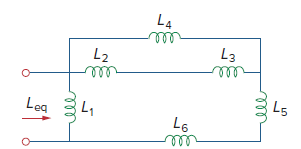
UsingFig. 6.74, design a problem to help other students better understand how inductors behave when connected in series and when connected in R parallel.Find Leq in the circuit of Fig. 6.74. L4 ll L3 L2 ll L5 Leg 3L, L6 ll all
A 6-V dc voltage is applied to an integrator with R = 50 kΩ, C = 100 μF at t = 0. How long will it take for the op amp to saturate if the saturation voltages are +12 V and −12 V? Assume that the initial capacitor voltage was zero.
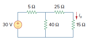
Calculate the current ioin the circuit ofFig. 4.69. What value of input voltage is necessary to make ioequal to 5 amps? 25 2 40 Ω 30 V 15Ω +)
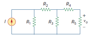
UsingFig. 4.70, design a problem to help other students better understand linearity.Find vo in the circuit of Fig. 4.70. If the source current is reduced to 1 μA. what is vo? R4 R2 Vo R5 R3 R, LO
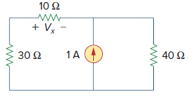
Use linearity and the assumption that Vo= 1 V to find the actual value of VoinFig. 4.75. 10 Ω + Vx - 30 Ω 1A 40 Ω
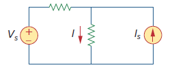
Given that I = 6 amps when Vs= 160 volts and Is= ˆ’10 amps and I = 5 amp when Vs= 200 volts and Is= 0, use superposition and linearity to determine the value of I when Vs= 120 volts and Is= 5 amps. Is
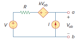
UsingFig. 4.78, design a problem to help other students better understand superposition.The letter k is a gain you can specify to make the problem easier to solve but must not be zero.For the circuit in Fig. 4.78, find the terminal voltage Vab using superposition. kVab +) Vob q어 +)
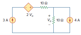
Use superposition to find Voin the circuit ofFig. 4.86. 10 2 2 V. V. 102 ) 4 A ЗА +.
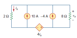
Use superposition to solve for vxin the circuit ofFig. 4.87. Vx 82 10 A -4 A 4ix 2.
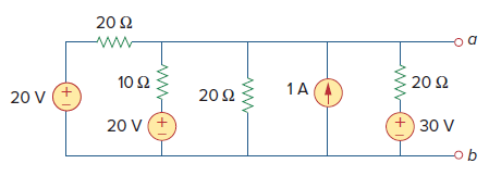
Use source transformation to reduce the circuit between terminals a and b shown inFig. 4.88 to a single voltage source in series with a single resistor. 20 Ω 10 Ω 20 Ω 1A 20Ω 20 V +. 30 V 20 v (+ ob
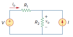
UsingFig. 4.89, design a problem to help other students better understand source transformation.Apply source transformation to determine vo and io in the circuit in Fig. 4.89. R, vo R2
For the circuit inFig. 4.90, use source transformation to find i. 5Ω 10Ω 2 A +) 20 V 5Ω 4Ω
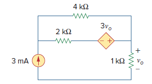
Use source transformation to find voin the circuit ofFig. 4.97. 4 k2 3vo 2 k2 Vo 1 k2 3 mA
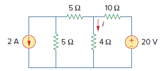
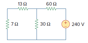
Determine the Thevenin equivalent circuit, shown inFig. 4.101, as seen by the 7-ohm resistor. Then calculate the current flowing through the 7-ohm resistor. 13Ω 60 Ω 7Ω 30 Ω 240 V +,
UsingFig. 4.102, design a problem that will help other students better understand Thevenin equivalent circuits.Find the Thevenin equivalent at terminals a-b of the circuit in Fig. 4.102. R3 R, R2 +)
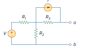
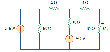
Apply Thevenin€™s theorem to find Voin the circuit ofFig. 4.105. Vo 10 Ω 16 2 2.5 A + 50 V
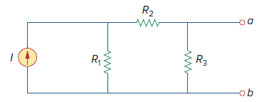
UsingFig. 4.113, design a problem to help other students better understand Norton equivalent circuits.Find the Norton equivalent at terminals a-b of the circuit in Fig. 4.113. R2 R1 R3 ob
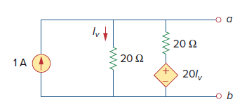
Obtain the Thevenin and Norton equivalent circuits of the circuit inFig. 4.114 with respect to terminals a and b. α 20 Ω 20 Ω 1A (4 201, ь
Determine the Norton equivalent at terminals a-b for the circuit inFig. 4.115. 10/, ww- 5 A
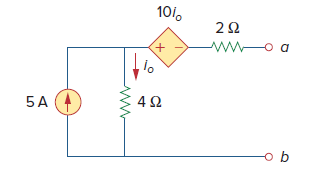
For the transistor model inFig. 4.118, obtain the Thevenin equivalent at terminals a-b. 3 k2 21 V (+ 201. 2 k2
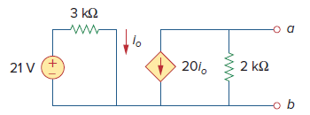
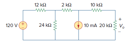
Use Norton€™s theorem to find Voin the circuit ofFig. 4.122. 12 k2 10 k2 2 k2 ww- 120 V (+ 24 k2 10 mA 20 k2{ V. +.
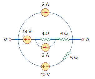
For the circuit inFig. 4.126, find the Thevenin and Norton equivalent circuits at terminals a-b. 2 A 18 V +- ЗА +) 10 V
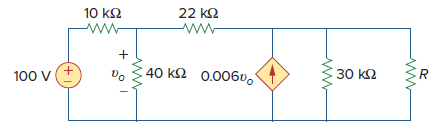
Find the maximum power transferred to resistor R in the circuit ofFig. 4.135. 22 k2 10 k2 40 k2 0.006v.1 +. 30 k2 100 V
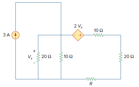
Determine the maximum power delivered to the variable resistor R shown in the circuit ofFig. 4.136. 2 Vx 10 Ω ЗА (4 20Ω 20Ω : 10 Ω ν. www
Showing 200 - 300
of 443
1
2
3
4
5
Step by Step Answers
![i(t) v(t) 12 2 8Ω 2[1- u(t)] A 2 H 18 + ?!](https://dsd5zvtm8ll6.cloudfront.net/si.question.images/images/question_images/1546/8/7/2/2085c336590ef7a91546854829360.jpg)
![5Ω 3[1– u(t)] A +) 45 V 50 mF 5 H i(t) elle](https://dsd5zvtm8ll6.cloudfront.net/si.question.images/images/question_images/1546/8/7/2/0095c3364c9522e51546854629715.jpg)
![10 Ω 10 Ω 5Ω 1A 10 Ω 25[1 – u(t)] V (+ :50 mF](https://dsd5zvtm8ll6.cloudfront.net/si.question.images/images/question_images/1546/7/0/2/0215c30ccc507e411546683075105.jpg)