New Semester
Started
Get
50% OFF
Study Help!
--h --m --s
Claim Now
Question Answers
Textbooks
Find textbooks, questions and answers
Oops, something went wrong!
Change your search query and then try again
S
Books
FREE
Study Help
Expert Questions
Accounting
General Management
Mathematics
Finance
Organizational Behaviour
Law
Physics
Operating System
Management Leadership
Sociology
Programming
Marketing
Database
Computer Network
Economics
Textbooks Solutions
Accounting
Managerial Accounting
Management Leadership
Cost Accounting
Statistics
Business Law
Corporate Finance
Finance
Economics
Auditing
Tutors
Online Tutors
Find a Tutor
Hire a Tutor
Become a Tutor
AI Tutor
AI Study Planner
NEW
Sell Books
Search
Search
Sign In
Register
study help
sciences
structural analysis
Genetics Analysis And Principles 7th Edition Robert Brooker - Solutions
Compare the structural features of a double-stranded RNA molecule with those of a DNA double helix.
What structural feature allows DNA to store information?
The total amount of G plus C in an organism’s DNA is 64% of the total base content of that DNA. What are the percentages of A, T, G, and C in the DNA?
Within a protein, certain amino acids are positively charged (e.g., lysine and arginine), some are negatively charged (e.g., glutamate and aspartate), some are polar but uncharged, and some are nonpolar. If you knew that a DNA-binding protein was recognizing the DNA backbone rather than a base
A double-stranded DNA molecule contains 560 nucleotides. How many complete turns occur in this double helix?
As the minor and major grooves wind around a DNA double helix, do they ever intersect each other, or do they always run parallel to each other?
The genetic material found within some viruses is single-stranded DNA. Would this genetic material contain equal amounts of A and T and equal amounts of G and C?
What chemical group (phosphate group, hydroxyl group, or a nitrogenous base) is found at the 3′ end of a DNA strand? What group is found at the 5′ end?
What is a bacterial nucleoid? With regard to cellular membranes, what is the difference between a bacterial nucleoid and a eukaryotic nucleus?
Describe the mechanisms by which bacterial DNA becomes compacted.
H ow are two topoisomers different from each other? How are they the same?
Describe the characteristics of highly repetitive DNA sequences.
If you were examining a sequence of chromosomal DNA, what characteristics would cause you to believe that the sequence contained a transposable element?
For insertion elements and simple transposons, what is the function of the inverted repeat sequences during transposition?
Do you consider TEs to be mutagens? In other words, do TEs cause mutations? Explain.
What is the difference between an autonomous element and a nonautonomous element? Is it possible for nonautonomous elements to move? If yes, explain how.
Explain how loop domains are formed.
In Figure 10.18, what are we looking at in part (b)? Is this an 11-nm fiber, a 30-nm fiber, or a 300-nm fiber? Does this DNA come from a cell during M phase or interphase? Figure 10.18: 0.5 m (b) H1 histone bound to linker region-nucleosomes more compact
What are the roles of the core histones and of histone H1 in the compaction of eukaryotic DNA?
Discuss the similarities and differences between constitutive heterochromatin and facultative heterochromatin.
Discuss the differences between the compaction level of metaphase chromosomes and that of interphase chromosomes.When would you expect gene transcription and DNA replication to take place, during M phase or interphase? Explain why.
What is an SMC complex? Describe two examples.
What key structural features of the DNA molecule underlie its ability to be accurately replicated?
With regard to DNA replication, define the term bidirectional replication.
Which of the following statements is not true? Explain why.A. A DNA strand can serve as a template strand on many occasions.B. Following semiconservative DNA replication, one strand is a newly made daughter strand and the other strand is a parental strand.C. A DNA double helix may contain two
Here are two strands of DNA:——————————————DNA polymerase→——————————————————————The one on the bottom is a template strand, and the one on the top is being synthesized by DNA polymerase in the direction shown by the arrow.
List and briefly describe the three types of functionally important sequences within bacterial origins of replication.
A short DNA sequence, which may be recognized by primase, is repeated many times throughout the E. coli chromosome. Researchers have hypothesized that primase may recognize this sequence as a site to begin the synthesis of an RNA primer for DNA replication. The E. coli chromosome is roughly 4.6
Single-strand binding proteins keep the two parental strands of DNA separated from each other until DNA polymerase has an opportunity to replicate the strands. Suggest how single-strand binding proteins keep the strands separated and yet do not impede the ability of DNA polymerase to replicate the
Make a drawing that illustrates how DNA helicase works.
If a eukaryotic chromosome has 25 origins of replication, how many replication forks does it have at the beginning of DNA replication?
In eukaryotes, what is meant by the term DNA replication licensing?How does the process occur?
Explain the central dogma of genetics at the molecular level.
In bacteria, what event marks the end of the initiation stage of transcription?
What is the consensus sequence for the following six DNA sequences?GGCATTGACT GCCATTGTCA CGCATAGTCA GGAAATGGGA GGCTTTGTCA GGCATAGTCA
A mutation within the DNA sequence of a certain gene changes the start codon to a stop codon. How will this mutation affect the transcription of this gene?
Describe what happens to the chemical bonding interactions when transcriptional termination occurs. Be specific about the type of chemical bonding.
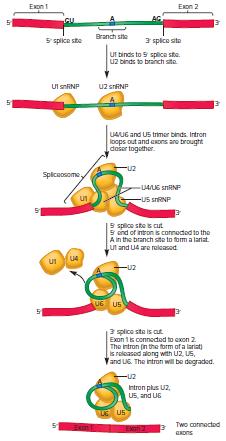
According to the mechanism shown in Figure 12.20, several snRNPs play different roles in the splicing of pre-mRNA. Identify the snRNP that recognizes each of the following sites:A. 5′ splice site B. 3′ splice site C. Branch siteFigure 12.20 h Exon 1 in Exon 2 13 5 splice site Branch site 3
A eukaryotic protein-encoding gene contains two introns and three exons: exon 1–intron 1–exon 2–intron 2–exon 3. The 5′ splice site at the boundary between exon 2 and intron 2 has been eliminated by a small deletion in the gene. Describe how the pre-mRNA encoded by this mutant gene will
In eukaryotes, what types of modifications occur to pre-mRNAs?
After the intron (which is in a lariat configuration) is released during pre-mRNA splicing, a brief moment occurs before the two exons are connected to each other. Which snRNP(s) hold(s) the exons in place so they can be covalently connected to each other?
The covalent attachment of an amino acid to a tRNA is an endergonic reaction. In other words, an input of energy is required for the reaction to proceed. Where does the energy needed to attach amino acids to tRNA molecules come from?
If a tRNA molecule carries a glutamic acid, what are the two possible anticodon sequences that it could contain? Be specific about the 5′ and 3′ ends.
A tRNA anticodon has the sequence 3′–GGU–5′. What amino acid does it carry?
In the tertiary structure of tRNA, where is the anticodon relative to the attachment site for the amino acid? Are these located adjacent to each other?
If a tRNA has the anticodon 3′–CCI–5′, what codon(s) can it recognize?
How and when does N-formylmethionine become attached to the initiator tRNA in bacteria?
How does a eukaryotic ribosome select its start codon? Describe the sequences in eukaryotic mRNAs that optimize start codon recognition.
What is the function of the nucleolus?
What is a polysome?
Lactose permease, a protein produced in E. coli, is composed of a single polypeptide that is 417 amino acids long. By convention, the amino acids within a polypeptide are numbered from the amino-terminus to the carboxyl-terminus. Are the following questions about lactose permease true or false?A.
An mRNA encodes a polypeptide that is 312 amino acids long.The 53rd codon in this polypeptide is a tryptophan codon. A mutation in the gene that encodes this polypeptide changes this tryptophan codon into a stop codon. How many amino acids would be in the resulting polypeptide: 52, 53, 259, or 260?
W hat is diauxic growth? Explain the roles of cAMP and CAP in this process.
What is antisense RNA? How does it affect the translation of a complementary mRNA?
List and describe three general ways that the functions of transcription factors can be modulated.
What are the functions of activator proteins and repressor proteins in transcription? Explain how these proteins work at the molecular level.
The binding of small effector molecules, protein-protein interactions, and covalent modifications are three common ways to modulate the activities of transcription factors. Which of these three mechanisms are used by steroid receptors and by the CREB protein?
The gene that encodes the enzyme called tyrosine hydroxylase is known to be activated by the CREB protein. Tyrosine hydroxylase is expressed in nerve cells and is involved in the synthesis of catecholamine, a neurotransmitter. The exposure of cells to adrenaline normally up-regulates the
Briefly describe three ways that ATP-dependent chromatinremodeling complexes may change chromatin structure.
Histones are thought to be displaced as RNA polymerase II is transcribing a gene. What would be the potentially harmful consequence if histones were not put back onto a gene after RNA polymerase II had passed?
Beginning with the binding of an activator protein at a nucleosome-free region, describe the steps that occur when a eukaryotic gene is transcribed.
Let’s suppose that a vertebrate organism carries a mutation that causes some cells that normally differentiate into nerve cells to differentiate into muscle cells. A molecular analysis reveals that this mutation is in a gene that encodes a DNA methyltransferase.Explain how an alteration in a DNA
List and briefly describe five types of molecular mechanisms that may underlie epigenetic gene regulation.
What are some key functions of heterochromatin?
With regard to chromosomal locations, how do constitutive and facultative heterochromatin differ?
Which of the following types of drugs would you expect to inhibit heterochromatin formation?A. A drug that inhibits DNA methyltransferase B. A drug that inhibits histone methyltransferase C. A drug that inhibits histone acetyltransferase D. A drug that inhibits histone deacetylase
Briefly describe three higher-order structures that occur in heterochromatin.
At the molecular level, what events promote the maintenance of heterochromatin formation during DNA replication and cell division?
List and briefly describe the three phases of heterochromatin formation at the chromosome level.
Let’s suppose a mutation removes the ICR next to the Igf2 gene. If this mutation is inherited from the mother, will the Igf2 gene (from the mother) be silenced or expressed? Explain.
Outline the molecular steps in the process of X-chromosome inactivation (XCI). Which step plays a key role in choosing which of the X chromosomes will remain active and which will be inactivated?
Describe the molecular steps by which polycomb group complexes cause epigenetic gene silencing.
Researchers have determined that environmental agents that do not cause gene mutations can contribute to cancer. Explain how.Would these epigenetic changes be passed to offspring?
Is paramutation a cis- or a trans-epigenetic mechanism?
If a winter-annual strain of Arabidopsis is grown in a greenhouse and not exposed to cold temperatures, its ability to flower is inhibited. Which gene is responsible for this inhibition?
Explain how the VIN3/PRC2 complex specifically binds to the FLC gene in Arabidopsis.
List and briefly describe four types of molecules that can bind to an ncRNA.
An ncRNA may have the following functions: scaffold, guide, alterer of protein function or stability, ribozyme, blocker, and/or decoy. Which of those functions is/are exhibited by each of the ncRNAs listed next? (A single ncRNA may have more than one function.)A. HOTAIR B. RNA of RNaseP C. microRNA
What is meant by the term RNA world? Describe observations and evidence that support this hypothesized period of life on Earth.From the perspective of living cells, what are the advantages of having had the RNA world be superseded by a DNA/RNA/protein world?
Explain how HOTAIR plays a role in the transcriptional regulation of particular genes.
What is the difference between an miRNA and an siRNA? How do these ncRNAs affect mRNAs?
Together with a specific set of proteins, snoRNAs direct the methylation or pseudouridylation of rRNAs. Does the snoRNA function as a scaffold, guide, ribozyme, blocker, decoy, and/or alterer of protein function or stability?
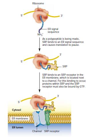
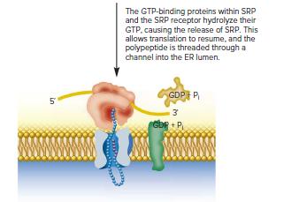
Look at Figure 17.8 and predict what would happen if the SRP RNA was unable to stimulate the GTPase activities of the GTPbinding proteins within SRP and the SRP receptor.Figure 17.8 5' 5 in in Ribosome Cytosol ER membrane 3 NH3 ER signal sequence As a polypeptide is being made, SRP binds to an ER
Describe the structure of SRP in eukaryotes, and outline its role in targeting proteins to the ER membrane.
Compare and contrast the roles of crRNA and tracrRNA in the defense against bacteriophages provided by the CRISPR-Cas system.
In the CRISPR-Cas system, does the tracrRNA act as a scaffold, guide, ribozyme, blocker, decoy, and/or alterer of protein function or stability?
What are the roles of Cas1, Cas2, and Cas9 proteins in bacterial genome defense?
With regard to pedigree analysis, make a list of observations that distinguish recessive, dominant, and X-linked patterns of inheritance.
Certain inherited forms of cancer, such as breast cancer involving the BRCA-1 gene, show a dominant pattern of inheritance in a family pedigree. However, at the cellular level, the mutant allele is actually recessive. Explain these two (seemingly contradictory) observations.
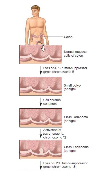
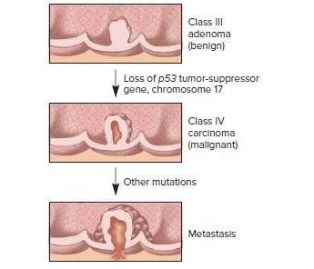
A random change in the sequence of a gene is more likely to result in a loss-of-function mutation rather than a gain-of-function mutation. Also, cancer usually results from multiple genetic changes, as illustrated in Figure 25.7. Based on these ideas, which kinds of cancer-causing mutation would
Describe how changes in chromosome structure and number may promote cancer.
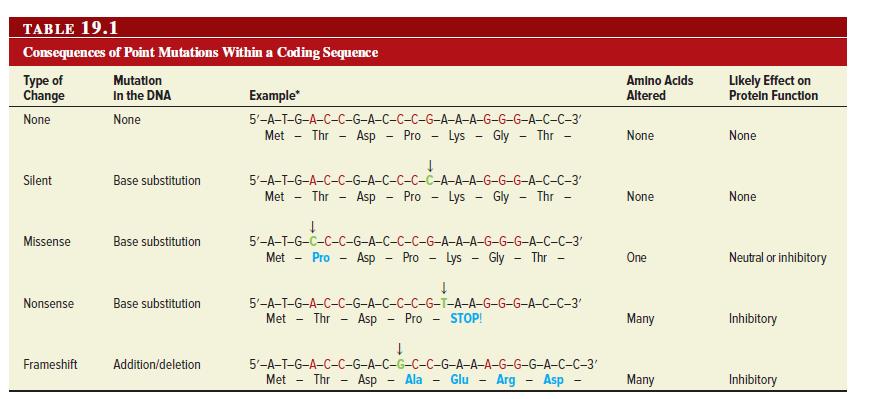
The effects of point mutations within the coding sequence of a gene are discussed in Chapter 19 (refer back to Table 19.1). For each of the following types of point mutations to promote cancer, would you expect the mutation to occur in a proto-oncogene, a tumor-suppressor gene, or either kind of
Which of the following mutations affecting proteins involved in the intracellular signaling pathway that is activated by epidermal growth factor (EGF) would you expect to promote cancer?A. A mutation that prevents GTP from binding to Ras B. A mutation that keeps MAPK active for a longer period of
List four types of genetic changes that commonly convert a protooncogene to an oncogene. Explain how the genetic changes are expected to alter the activity of the gene product.
What is the difference between an oncogene and a tumorsuppressor gene? Give two examples of each type of gene.
Identify the key properties of cancer cells that distinguish them from noncancerous (normal) cells.
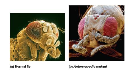
Based on the photographs in Figure 26.13, in which segment(s) is the Antp gene normally expressed?Figure 26.13: (a) Normal fly (b) Antennapedia mutant
Most genes encode polypeptides, which are functional units of proteins. Explain how the structure and function of proteins produce an organism’s traits.
What is the cause of Down syndrome?
The text describes how the detrimental symptoms associated with the disease phenylketonuria (PKU) are caused by a faulty gene. However, a change in diet can prevent these symptoms.Pick a trait of your favorite plant species, and explain how genetics and the environment may play important roles in
Showing 400 - 500
of 1426
1
2
3
4
5
6
7
8
9
10
11
12
13
14
15
Step by Step Answers