

Consider the MOSFET diff-amp shown in Figure P11.63. The bias voltages are (V^{+}=3 mathrm{~V}) and (V^{-}=-3 mathrm{~V}).
Question:
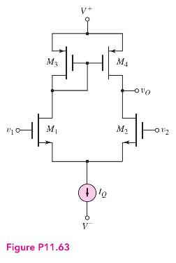
Consider the MOSFET diff-amp shown in Figure P11.63. The bias voltages are \(V^{+}=3 \mathrm{~V}\) and \(V^{-}=-3 \mathrm{~V}\). The current source is \(I_{Q}=200 \mu \mathrm{A}\) and has an output resistance of \(R_{o}=2 \mathrm{M} \Omega\). The transistor parameters are \(V_{T N}=0.4 \mathrm{~V}, V_{T P}=-0.4 \mathrm{~V}, K_{n}=K_{p}=0.5 \mathrm{~mA} / \mathrm{V}^{2}, \lambda_{2}=0.02 \mathrm{~V}, \mathrm{~V}^{-1}\), \(\lambda_{4}=0.03 \mathrm{~V}^{-1}\) and \(\lambda_{1}=\lambda_{3}=0\).
(a) Determine the voltage gain \(A=v_{o} / v_{d}\) for \(v_{1}=v_{d}\) and \(v_{2}=0\).
(b) Determine the voltage gain \(A=v_{o} / v_{d}\) for \(v_{1}=0\) and \(v_{2}=-v_{d}\).
(c) Determine the voltage gain \(A=v_{o} / v_{d}\) for \(v_{1}=v_{d} / 2\) and \(v_{2}=-v_{d} / 2\)
Step by Step Answer:


Microelectronics Circuit Analysis And Design
ISBN: 9780071289474
4th Edition
Authors: Donald A. Neamen
