

Consider the differential amplifier shown in Figure P11.3 with transistor parameters (beta=150, V_{B E}() on ()=0.7 mathrm{~V}),
Question:
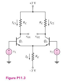
Consider the differential amplifier shown in Figure P11.3 with transistor parameters \(\beta=150, V_{B E}(\) on \()=0.7 \mathrm{~V}\), and \(V_{A}=\infty\).
(a) Design the circuit such that the \(Q\)-point values are \(I_{C 1}=I_{C 2}=100 \mu \mathrm{A}\) and \(v_{O 1}=\) \(v_{O 2}=1.2 \mathrm{~V}\) for \(v_{1}=v_{2}=0\).
(b) Draw the dc load line and plot the \(Q\)-point for transistor \(Q_{2}\).
(c) What are the maximum and minimum values of the common-mode input voltage?
Step by Step Answer:

This question has not been answered yet.
You can Ask your question!
Related Book For 

Microelectronics Circuit Analysis And Design
ISBN: 9780071289474
4th Edition
Authors: Donald A. Neamen
Question Posted:
