

Design an emitter-follower circuit with the configuration shown in Figure 6.49 such that the input resistance (R_{i}),
Question:
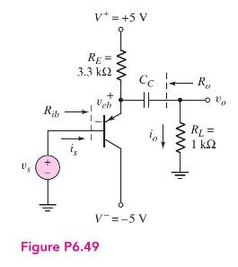
Design an emitter-follower circuit with the configuration shown in Figure 6.49 such that the input resistance \(R_{i}\), as defined in Figure 6.51, is \(120 \mathrm{k} \Omega\). Assume transistor parameters of \(\beta=120\) and \(V_{A}=\infty\). Let \(V_{C C}=5 \mathrm{~V}\) and \(R_{E}=2 \mathrm{k} \Omega\). Find new values of \(R_{1}\) and \(R_{2}\). The \(Q\)-point should be approximately in the center of the load line.
Fantastic news! We've Found the answer you've been seeking!
Step by Step Answer:

Answered By
Jeff Omollo
As an educator I have had the opportunity to work with students of all ages and backgrounds. Throughout my career, I have developed a teaching style that encourages student engagement and promotes active learning. My education and tutoring skills has enabled me to empower students to become lifelong learners.
5+ Reviews
49+ Question Solved
Related Book For 

Microelectronics Circuit Analysis And Design
ISBN: 9780071289474
4th Edition
Authors: Donald A. Neamen
Question Posted:
