

The bias voltages of the diff-amp circuit shown in Figure 11.19 are (V^{+}=5 mathrm{~V}) and (V^{-}=-5 mathrm{~V}),
Question:
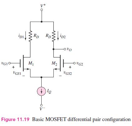
The bias voltages of the diff-amp circuit shown in Figure 11.19 are \(V^{+}=5 \mathrm{~V}\) and \(V^{-}=-5 \mathrm{~V}\), and the bias current is \(I_{Q}=0.2 \mathrm{~mA}\). The transistor parameters are \(V_{T N}=0.4 \mathrm{~V}, K_{n}=0.15 \mathrm{~mA} / \mathrm{V}^{2}\), and \(\lambda=0\).
(a) Design the circuit such that a differential-mode output voltage of \(\Delta v_{O}=0.5 \mathrm{~V}\) is produced when a differential-mode input voltage of \(v_{d}=v_{1}-v_{2}=100 \mathrm{mV}\) is applied.
(b) Using the results of part (a), determine the maximum possible common-mode input voltage that can be applied such that the transistors remain biased in the saturation region.
Step by Step Answer:


Microelectronics Circuit Analysis And Design
ISBN: 9780071289474
4th Edition
Authors: Donald A. Neamen
