

The circuit and transistor parameters for the circuit shown in Figure P11.11 are (V^{+}=5 mathrm{~V}, V^{-}=-5 mathrm{~V},
Question:
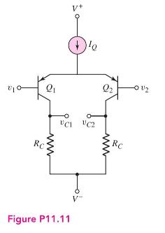
The circuit and transistor parameters for the circuit shown in Figure P11.11 are \(V^{+}=5 \mathrm{~V}, V^{-}=-5 \mathrm{~V}, I_{Q}=0.2 \mathrm{~mA}, \beta=80, V_{E B}(\) on \()=0.6 \mathrm{~V}\), and \(V_{A}=\infty\).
(a) Design the circuit such that the minimum common-mode voltage is \(v_{c m}=-2.5 \mathrm{~V}\).
(b) Using the results of part (a), what is the magnitude of the differential-mode gain, \(A_{d}=\left|\left(v_{C 1}-v_{C 2}\right) /\left(v_{1}-v_{2}\right)\right|\) ?
(c) Determine \(v_{C 1}\) and \(v_{C 2}\) for \(v_{1}=0.507 \mathrm{~V}\) and \(v_{2}=0.493 \mathrm{~V}\).
(d) What is the minimum output resistance of the current source such that \(\mathrm{CMRR}_{\mathrm{dB}}=60 \mathrm{~dB}\) for a one-sided output.
Step by Step Answer:


Microelectronics Circuit Analysis And Design
ISBN: 9780071289474
4th Edition
Authors: Donald A. Neamen
