

The differential amplifier in Figure P11.64 has a pair of PMOS transistors as input devices and a
Question:
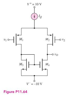
The differential amplifier in Figure P11.64 has a pair of PMOS transistors as input devices and a pair of NMOS transistors connected as an active load. The circuit is biased with \(I_{Q}=0.2 \mathrm{~mA}\), and the transistor parameters are: \(K_{n}=K_{p}=0.1 \mathrm{~mA} / \mathrm{V}^{2}, \quad \lambda_{n}=0.01 \mathrm{~V}^{-1}, \quad \lambda_{p}=0.015 \mathrm{~V}^{-1}\), \(V_{T N}=1 \mathrm{~V}\), and \(V_{T P}=-1 \mathrm{~V}\).
(a) Determine the quiescent drain-tosource voltage in each transistor.
(b) Find the open-circuit differentialmode voltage gain.
(c) What is the output resistance?
Fantastic news! We've Found the answer you've been seeking!
Step by Step Answer:

Answered By
Qurat Ul Ain
Successful writing is about matching great style with top content. As an experienced freelance writer specialising in article writing and ghostwriting, I can provide you with that perfect combination, adapted to suit your needs.
I have written articles on subjects including history, management, and finance. Much of my work is ghost-writing, so I am used to adapting to someone else's preferred style and tone. I have post-graduate qualifications in history, teaching, and social science, as well as a management diploma, and so am well equipped to research and write in these areas.
265+ Reviews
421+ Question Solved
Related Book For 

Microelectronics Circuit Analysis And Design
ISBN: 9780071289474
4th Edition
Authors: Donald A. Neamen
Question Posted:
