

In the finite element model of a plane truss in problem 21, the lengths of elements 1
Question:
In the finite element model of a plane truss in problem 21, the lengths of elements 1 and 2 are \(1 \mathrm{~m}\) and \(\sqrt{2} \mathrm{~m}\), respectively. The axial rigidity of the elements is \(E A=10^{7} \mathrm{~N}\).
a. Fill in the connectivity information of your choice
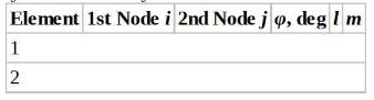
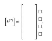
b. Write down the element stiffness matrix \(\left[k^{(2)}ight]\) of element 2 with DOFs.
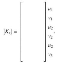
c. Show where \(\left[k^{(2)}ight]\) will be placed in the structural stiffness matrix \(\left[K_{s}ight]\).
d. The displacements are calculated as: \(u_{1}=+5 \mathrm{~mm}, v_{1}=-5 \sqrt{2} \mathrm{~mm}\). Use your connectivity information to calculate the element force \(P\) in element 2.
Data From Problem 21:
The truss structure shown in the figure supports a force \(F\). The finite element method is used to analyze this structure using two truss elements as shown in the figure. The cross sectional area for both elements is \(A=2 \mathrm{in}^{2}\), and the lengths are \(L^{(2)}=10 \mathrm{ft}\). Young's Modulus of the material \(\mathrm{E}=30 \times 10^{6} \mathrm{psi}\).
Step by Step Answer:


Introduction To Finite Element Analysis And Design
ISBN: 9781119078722
2nd Edition
Authors: Nam H. Kim, Bhavani V. Sankar, Ashok V. Kumar
