

The truss structure shown in the figure supports the force (F). The finite element method is used
Question:
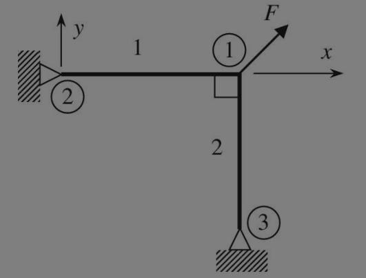
The truss structure shown in the figure supports the force \(F\). The finite element method is used to analyze this structure using two truss elements as shown. The area of crosssection (for all elements) \(A=2 \mathrm{in}^{2}\), and Young's modulus \(E=30 \times 10^{6}\) psi. Both elements are of equal length \(L=10 \mathrm{ft}\).
a. Compute the transformation matrix for elements 1 and 2 between the global coordinate system and the local coordinate system for each element.
b. Compute the stiffness matrix for the elements 1 and 2 .
c. Assemble the structural matrix equation \(\left[\mathbf{K}_{s}ight]\left\{\mathbf{Q}_{s}ight\}=\left\{\mathbf{F}_{s}ight\}\) (without applying the boundary conditions).
d. It is determined after solving the final equations that the displacement components of node 1 are: \(u_{1 x}=1.5 \times 10^{-2}\) in., \(u_{1 y}=-0.5 \times 10^{-2}\) in. Compute the applied load \(F\).
e. Compute stress and strain in element 1.
Step by Step Answer:


Introduction To Finite Element Analysis And Design
ISBN: 9781119078722
2nd Edition
Authors: Nam H. Kim, Bhavani V. Sankar, Ashok V. Kumar
