

Question: The following diagram shows a control system with conditional feedback. The transfer function (G(s)) denotes the controlled process, and (D(s)) and (H(s)) are the controller
The following diagram shows a control system with conditional feedback. The transfer function \(G(s)\) denotes the controlled process, and \(D(s)\) and \(H(s)\) are the controller transfer functions.
(a) Derive the transfer functions \(Y(s) /\left.R(s)ight|_{N=0}\) and \(Y(s) /\left.N(s)ight|_{R=0}\).
(b) Find \(Y(s) /\left.R(s)ight|_{N=0}\) when \(D(s)=G(s)\).
(c) Let \[
G(s)=D(s)=\frac{100}{(s+1)(s+5)}
\]
and find the output response \(y(t)\) when \(N(s)=0\) and \(r(t)=1(t)\) (a unit step function).
(d) With \(G(s)\) and \(D(s)\) as given in part (c), select among the following choices of \(H(s)\) such that when \(n(t)=1(t)\) and \(r(t)=0\), the steady-state value of \(y(t)\) is equal to zero. (There may be multiple answers.)
\[
\begin{array}{rr}
H(s)=\frac{10}{s(s+1)} & H(s)=\frac{10}{(s+1)(s+2)} \\
H(s)=\frac{10(s+1)}{(s+2)} & H(s)=\frac{K}{s^{n}}(n=\text { positive integer, select } n)
\end{array}
\]
It is important to note that the poles of the closed-loop system must all be in the left half s-plane for the Final Value Theorem to be valid.
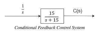
1S 15 s+15 C(s) Conditional Feedback Control System
Step by Step Solution
3.40 Rating (162 Votes )
There are 3 Steps involved in it

Get step-by-step solutions from verified subject matter experts