

Question: PowerWorld Simulator case Problem 11_28 duplicates Example 11.11 except the wind turbine generator is set so it is initially supplying (100 mathrm{MW}) to the infinite
PowerWorld Simulator case Problem 11_28 duplicates Example 11.11 except the wind turbine generator is set so it is initially supplying \(100 \mathrm{MW}\) to the infinite bus at unity power factor.
(a) Use the induction machine equations to verify the initial conditions of \(\mathrm{S}=-0.0129, \mathrm{E}_{r}^{\prime}=0.8475\), \(\mathrm{E}_{i}^{\prime}=0.4230, \mathrm{I}_{\mathrm{r}}=0.8433\), and (\mathrm{I}_{\mathrm{i}}=0.7119\).
(b) Plot the terminal voltage for the fault sequence from Example 11.6.
Example 11.11
For the system from Example 11.3, assume the synchronous generator is replaced with an induction generator and shunt capacitor in order to represent a wind farm with the same initial real and reactive power output as in Example 11.3. The induction generator parameters are \(\mathrm{H}=0.9\) per unit-seconds, \(\mathrm{R}_{a}=0.013, \mathrm{X}_{a}=\) \(0.067, \mathrm{X}_{m}=3.8, \mathrm{R}_{1}=0.0124, \mathrm{X}_{1}=0.17\) (all per unit using the 100 MVA system base). This system is modeled in PowerWorld Simulator case Example 11_11.
Example 11.6
The synchronous generator in Figure 11.4 is initially operating in the steady-state condition given in Example 11.3 when a permanent three-phase-to-ground bolted short circuit occurs on line 1-3 at bus 3 . The fault is cleared by opening the circuit breakers at the ends of line \(1-3\) and line \(2-3\). These circuit breakers then remain open. Calculate the critical clearing angle. As in previous examples, \(\mathrm{H}=\) 3.0 p.u.-s, \(p_{m}=1.0\) per unit and \(\omega_{\text {p.u. }}=1.0\) in the swing equation.
Figure 11.4
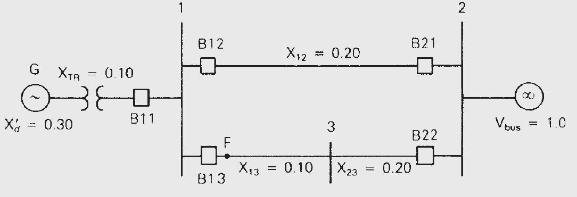
G XTR X = 0.30 - 0.10 E B11 1 B12 F 0 813 X12 X13 = 0.10 = 0.20 3 tx X23 = 0.20 B21 B22 2 Vous = 1.C
Step by Step Solution
3.48 Rating (145 Votes )
There are 3 Steps involved in it

Get step-by-step solutions from verified subject matter experts