

The input to the circuit in Figure P13=3 3 is: [ v_{mathrm{S}}(t)=25 cos 2000 t+5 cos 10,000
Question:
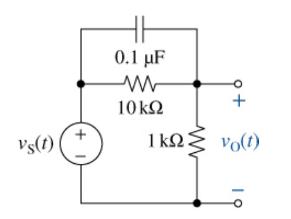
The input to the circuit in Figure P13=3 3 is:
\[
v_{\mathrm{S}}(t)=25 \cos 2000 t+5 \cos 10,000 t \mathrm{~V}
\]
(a) Find the transfer function \(T(s)=V_{\mathrm{O}}(s) / V_{\mathrm{S}}(s)\).
(b) Calculate the average power delivered to the \(1-\mathrm{k} \Omega\) load resistor.
(c) Use Multisim to find the magnitude of the voltage across the load resistor for each of the two inputs. Then apply Eq.(13-24) to find \(V \mathrm{rms}\) and \(\mathrm{Eq} .(13-25)\). to find the average power delivered to the load.
(d) Do a transient analysis with both sources connected and have Multisim calculate the average power, "avg(P(R2))," dissipated in the 1-k \(\Omega\) load (R2). Be sure to let the circuit reach steady state before measuring the average power. Compare your answer with that found in Part (b).
Step by Step Answer:
a b c d Use nodevoltage analysis at ...View the full answer


The Analysis And Design Of Linear Circuits
ISBN: 9781119913023
10th Edition
Authors: Roland E. Thomas, Albert J. Rosa, Gregory J. Toussaint
