

Question: For the feedback circuit in Fig. 12.46 using the op amp in Fig. 12.40, the capacitor values are C 1 = C 2 = 4
Fig. 12.46:
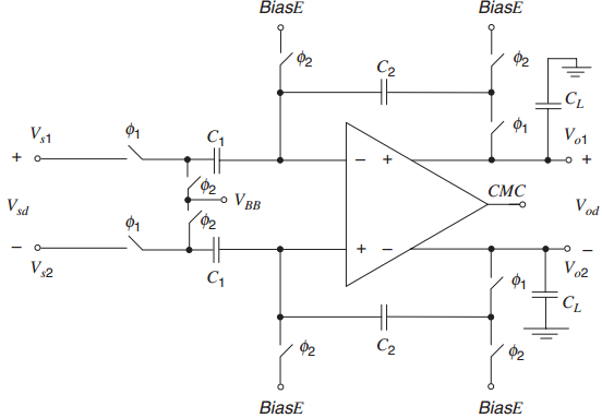
Fig. 12.40:
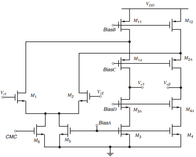
BiasE BiasE 2 C2 CL Vo1 01 V,1 CMC V od 92 o VBB 2 V sd 1 V02 C1 C1 V32 42 C2 $2 BiasE BiasE VpD M12 M11 BiasB M2A M1A BiasC Vo1 Vo2 V1 M1 M2 M4A BiasD BiasA M4 CMC M5 M6
Step by Step Solution
★★★★★
3.39 Rating (165 Votes )
There are 3 Steps involved in it
1 Expert Approved Answer
Step: 1 Unlock

The DM slew rate is given by 12192 ... View full answer
Question Has Been Solved by an Expert!
Get step-by-step solutions from verified subject matter experts
Step: 2 Unlock
Step: 3 Unlock
Document Format (2 attachments)
1528_605d88e1be240_686988.pdf
180 KBs PDF File
1528_605d88e1be240_686988.docx
120 KBs Word File