Figure P5.62 illustrates two relief valves. The valve disk is designed to lift when the upstream pressure
Question:
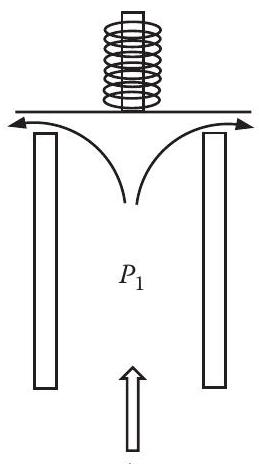
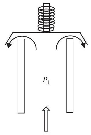
Figure P5.62 illustrates two relief valves. The valve disk is designed to lift when the upstream pressure in the vessel $\left(P_{1}\right)$ reaches the valve set pressure. Valve $\mathrm{A}$ has a disk that diverts the fluid leaving the valve by $90^{\circ}$ (i.e., to the horizontal direction), whereas the disk in valve B diverts the fluid to a direction that is $60^{\circ}$ downward from the horizontal. The diameter of the valve nozzle is 3 in., and the clearance between the end of the nozzle and the disk is $1 \mathrm{in}$., for both valves. If the fluid is water at $200^{\circ} \mathrm{F}, P_{1}=100 \mathrm{psig}$, and the discharge pressure is atmospheric, determine the force exerted on the disk for both cases A and B. The loss coefficient for the valve in both cases is 2.4 based on the velocity in the nozzle.
Figure P5.62
A
B
Transcribed Image Text:
N P1
Fantastic news! We've Found the answer you've been seeking!
Step by Step Answer:
Answer rating: 100% (QA)
Answered By
Nicholas Maina
Throughout my tutoring journey, I've amassed a wealth of hands-on experience and honed a diverse set of skills that enable me to guide students towards mastering complex subjects. My proficiency as a tutor rests on several key pillars:
1. Subject Mastery:
With a comprehensive understanding of a wide range of subjects spanning mathematics, science, humanities, and more, I can adeptly explain intricate concepts and break them down into digestible chunks. My proficiency extends to offering real-world applications, ensuring students grasp the practical relevance of their studies.
2. Individualized Guidance:
Recognizing that every student learns differently, I tailor my approach to accommodate various learning styles and paces. Through personalized interactions, I identify a student's strengths and areas for improvement, allowing me to craft targeted lessons that foster a deeper understanding of the material.
3. Problem-Solving Facilitation:
I excel in guiding students through problem-solving processes and encouraging critical thinking and analytical skills. By walking learners through step-by-step solutions and addressing their questions in a coherent manner, I empower them to approach challenges with confidence.
4. Effective Communication:
My tutoring proficiency is founded on clear and concise communication. I have the ability to convey complex ideas in an accessible manner, fostering a strong student-tutor rapport that encourages open dialogue and fruitful discussions.
5. Adaptability and Patience:
Tutoring is a dynamic process, and I have cultivated adaptability and patience to cater to evolving learning needs. I remain patient through difficulties, adjusting my teaching methods as necessary to ensure that students overcome obstacles and achieve their goals.
6. Interactive Learning:
Interactive learning lies at the heart of my approach. By engaging students in discussions, brainstorming sessions, and interactive exercises, I foster a stimulating learning environment that encourages active participation and long-term retention.
7. Continuous Improvement:
My dedication to being an effective tutor is a journey of continuous improvement. I regularly seek feedback and stay updated on educational methodologies, integrating new insights to refine my tutoring techniques and provide an even more enriching learning experience.
In essence, my hands-on experience as a tutor equips me with the tools to facilitate comprehensive understanding, critical thinking, and academic success. I am committed to helping students realize their full potential and fostering a passion for lifelong learning.