

Question: A chamber temperature control system is modeled as shown in Fig. P9.2-3. This system is described in Problem 1.6-1. For this problem, ignore the disturbance
A chamber temperature control system is modeled as shown in Fig. P9.2-3. This system is described in Problem 1.6-1. For this problem, ignore the disturbance input, T=0.6 sT=0.6 s, and let D(z)=1D(z)=1. It was shown in Problem 6.2-4 that
((0.04)z−1zz[2s(s+0.5)]=0.04147z−0.7408
Note that the sensor gain is included in this transfer function.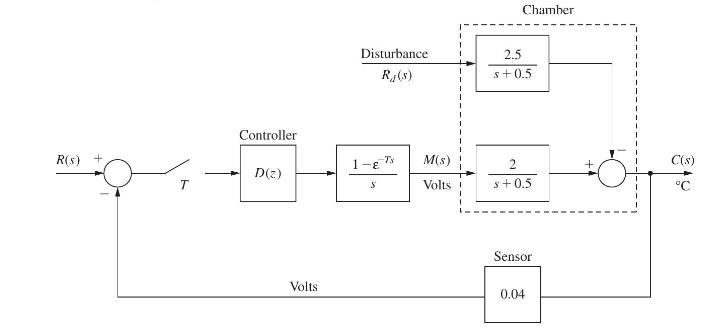
(a) Draw a flow graph of the plant and sensor. Write the state equations with the state variable x(k)x(k) equal to the system output and the output y(k)y(k) equal to the sensor output.
(b) Find the time constant ττ for this closed-loop system.
(c) Using pole-placement design, find the gain KK that yield the closed-loop time constant τ=1 sτ=1 s. Note that the sensor gain does not enter these calculations.
(d) Show that the gain KK in part (b) yields the desired closed-loop characteristic equation, using (915).
(e) Draw a block diagram for the system that includes the sensor. Let the digital computer realize a gain, K1K1, such that the closed-loop time constant is as given in part (b). The sensor in this system must have the gain given.
(f) Using the characteristic equation for the block diagram of part (e),
1+K1G(z)H=01+K1G(z)H=0
verify that this block diagram yields the desired characteristic equation.
Problem 1.6-1![It is shown in [6] that given the partitioned matrix H = E F G where each partition is n X n, the](https://dsd5zvtm8ll6.cloudfront.net/images/question_images/1705/5/8/0/41365a9177d8f9bf1705580413336.jpg)
Problem 6.2-4
Shown in Fig. P6.2-4 is the block diagram of a temperature control system for a large test chamber. This
system is described in Problem 1.6-1. Ignore the disturbance input for this problem.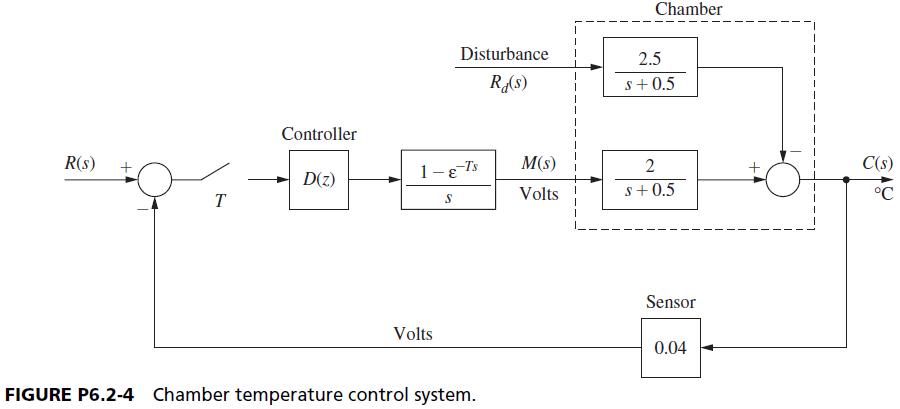
R(s) + Controller D(z) Volts Disturbance R, (s) 1-E S Ts M(s) Volts Chamber 2.5 s+0.5 2 s+0.5 Sensor 0.04 C(s)
Step by Step Solution
3.54 Rating (158 Votes )
There are 3 Steps involved in it
Thanks for sharing the images Ill help you with each part of the problem stepbystep Heres how I will ... View full answer

Get step-by-step solutions from verified subject matter experts