

Consider the chamber temperature control system of Problem 8.4-3. Suppose that a variable gain (K) is added
Question:
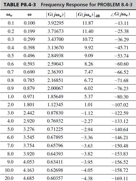
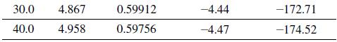
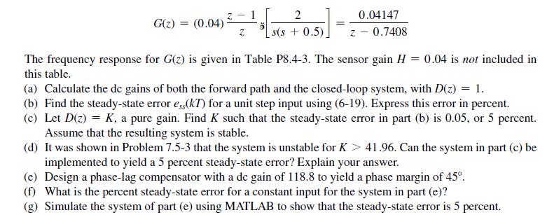
Consider the chamber temperature control system of Problem 8.4-3. Suppose that a variable gain \(K\) is added to the plant. The pulse transfer function for this system is given in Problem 8.4-3.
(a) Plot the root locus for this system and find the value of \(K>0\) for which the system is stable.
(b) Find the time constant for the system with \(K=1\).
(c) Design a phase-lag controller such that the characteristic-equation root is approximately the same as that in part (b) but for the gain \(K=3\). Hint: Choose \(z_{p}=0.999\).
(d) Find the steady-state errors for both the uncompensated system of part (b) and the compensated system of part (c).
(e) By computer, verify the design in part (c) by finding the characteristic-equation roots.
Problem 8.4-3
Shown in Fig. P8.4-3 is the block diagram of the temperature control system described in Problem 1.6-1.
For this problem, ignore the disturbance input. In Fig. P8.4-3 the sensor gain of H = 0.04 has been shifted
into the forward path to yield a unity feedback system. The stability characteristics are unchanged, since
the loop transfer function has not changed. Note that c(t) is the chamber temperature in degrees Celsius. It
is shown in Problem 6.2-4 that with T = 0.6, the function G(z)H is given by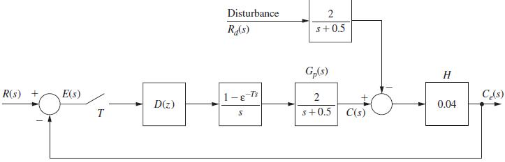
Problem 1.6-1![It is shown in [6] that given the partitioned matrix H = D E F G where each partition is n Xn, the](https://dsd5zvtm8ll6.cloudfront.net/images/question_images/1705/5/7/1/67465a8f55af2df11705571674305.jpg)
Step by Step Answer:

This question has not been answered yet.
You can Ask your question!

Digital Control System Analysis And Design
ISBN: 9780132938310
4th Edition
Authors: Charles Phillips, H. Nagle, Aranya Chakrabortty
