

Question: A satellite control system is modeled as shown in Fig. P11.4-6. This system is described in Problem 1.4-1. For this problem, ignore the sensor gain
A satellite control system is modeled as shown in Fig. P11.4-6. This system is described in Problem 1.4-1.
For this problem, ignore the sensor gain and let D(z) = 1. In addition, K = 1, T = 1 s, and J = 4. As stated in Problem 9.2-4, a state model for this system is given by![- [6 1] x(4) + [0.235 x(k + 1) = y(k) [10]x(k) = u(k)](https://dsd5zvtm8ll6.cloudfront.net/images/question_images/1705/6/4/5/77565aa16cfbc2801705645774653.jpg)
where x1(k) is angular position and x2(k) is angular velocity.
(a) Determine by hand the gains required to minimize the cost function k=0 x(K) x(k) + 2u(k)](https://dsd5zvtm8ll6.cloudfront.net/images/question_images/1705/6/4/5/81465aa16f675a241705645813516.jpg)
with N = 1. The value of N is chosen to be unity to limit the calculations.
(b) Use MATLAB to solve part (a) for N = 20. Sketch the calculated gains versus k.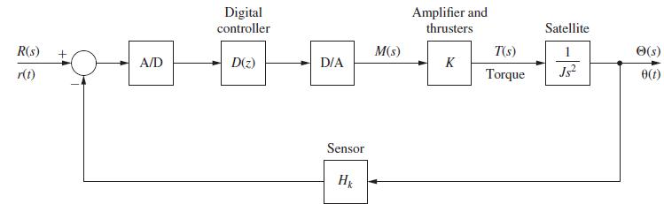
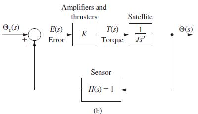
Problem 1.4-1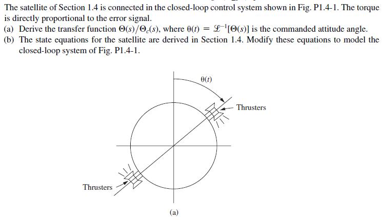
- [6 1] x(4) + [0.235 x(k+ 1) = y(k) [10]x(k) = u(k)
Step by Step Solution
3.37 Rating (144 Votes )
There are 3 Steps involved in it
aQ11P b P1 R2 K1 00 B P1B RB B... View full answer

Get step-by-step solutions from verified subject matter experts