

Question: A satellite control system is modeled as shown in Fig. P9.2-4. This system is described in Problem 1.4-1. For this problem, let D ( z
A satellite control system is modeled as shown in Fig. P9.2-4. This system is described in Problem 1.4-1. For this problem, let D(z)=1K=1,T=1 s,J=4. In addition, K=1,T=1 s,J=4Hk=1, and Hk=1z. From the zz−1zz[14s3]=0.125(z+1)(z−1)2-transform tables,
z−1zz[14s3]=0.125(z+1)(z−1)2x(k+1)=[1101]x(k)+[0.1250.25]u(k)y(k)=[10]x(k)
A state model for this system is given by
x(k+1)=[1101]x(k)+[0.1250.25]u(k)y(k)=[10]x(k)x1(k)
where x1(k)x2(k) is angular position and x2(k)K is angular velocity.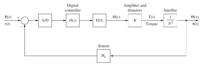
(a) Show that the closed-loop system is unstable.
(b) Using pole-placement design, find the gain matrix Kζ=0.707 that yields the closed-loop damping ratio ζ=0.707τ=4 s and the time constant τ=4 sK.
(c) Show that the gain matrix KDce(z) in part (b) yields the desired closed-loop characteristic equation, using (9-15).
Equation 9-15![]()
Problem 1.4-1
Given that (11-21) and (11-22) are valid, derive (11-23).
Equation 11-21![]()
Equation 11-22![]()
Equation 11-23![]()
R(s) + A/D Digital controller D(z) D/A Sensor Hk M(s) Amplifier and thrustors K T(S) Torque Satellite 1 Js (s) 8(1)
Step by Step Solution
3.54 Rating (154 Votes )
There are 3 Steps involved in it
a b 1 KGz H01 1 0 012521 z 2z1 z 1875z 1125 0 zero... View full answer

Get step-by-step solutions from verified subject matter experts