

Consider the system of Example 8.1. (a) Design a PI filter to achieve a phase margin of
Question:
Consider the system of Example 8.1.
(a) Design a PI filter to achieve a phase margin of \(60^{\circ}\).
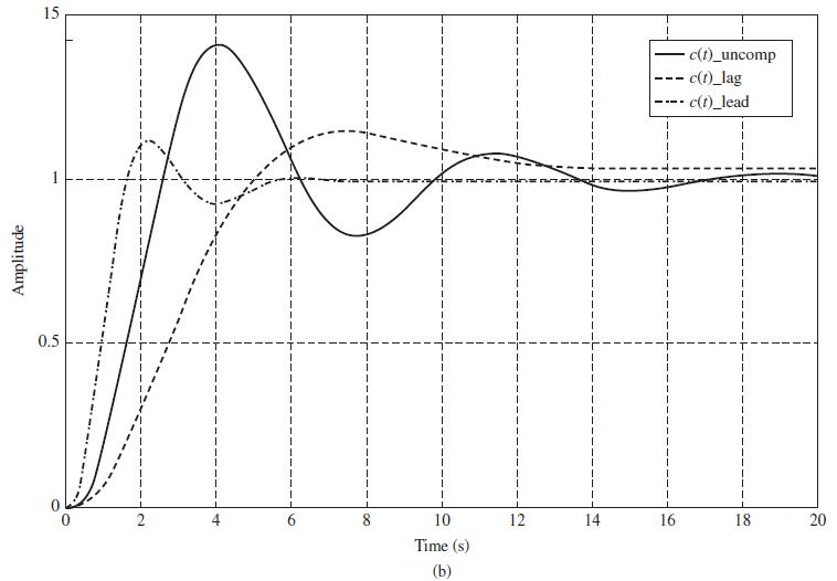
(b) Obtain the system step response using MATLAB. Compare this response to that of the system of Example 8.1, which is plotted in Fig. 8-14.
Example 8.1
We will consider the design of a servomotor system as described in Section 1.5. Suppose that
the servo is to control the horizontal (azimuth) angle for pointing a radar antenna. Then, in the
closed-loop system of Fig. 8-6, c(t) is the azimuth angle of the antenna, and r(t) is the commanded,
or desired, azimuth angle. The plant transfer function derived in Section 1.5 is second
order; however, we will assume that the armature inductance cannot be neglected, resulting in a
third-order transfer function. Then suppose that the parameters of the plant are such that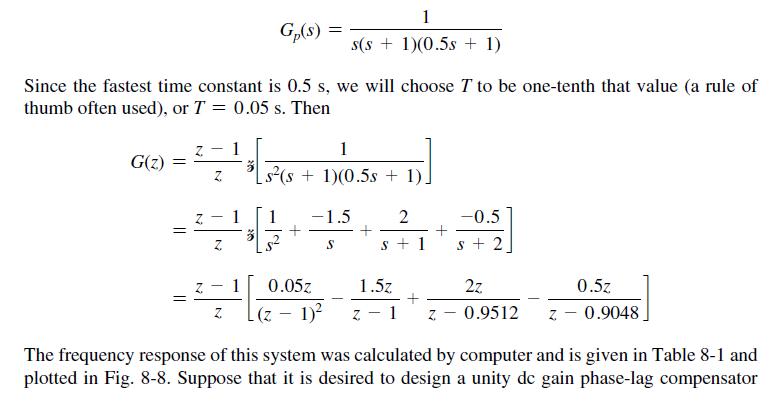
Fig. 8-6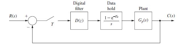
Fig. 8-14
Step by Step Answer:


Digital Control System Analysis And Design
ISBN: 9780132938310
4th Edition
Authors: Charles Phillips, H. Nagle, Aranya Chakrabortty
