

Question: The state-variable model of a servomotor is given in Section 1.5. Expand these state equations to model the antenna pointing system of Problem 1.5-1(b). Problem
The state-variable model of a servomotor is given in Section 1.5. Expand these state equations to model the antenna pointing system of Problem 1.5-1(b).
Problem 1.5-1(b)
The system block diagram is given in Fig. P1.5-1(b), with the angle signals shown in degrees and the voltages in volts. Add the required gains and the transfer functions to this block diagram.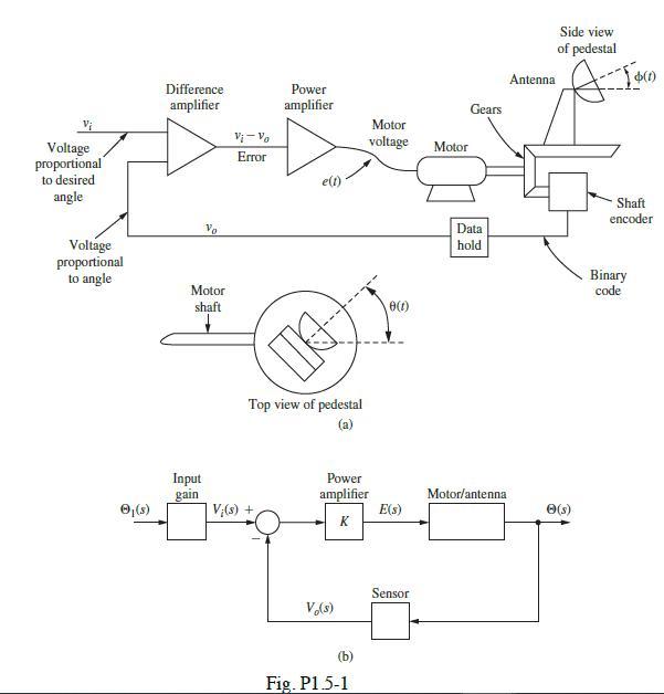
Voltage proportional to desired angle Voltage proportional to angle (s) Difference amplifier Vo Motor shaft Input gain Vi-Vo Error Power amplifier V(s) + e(1) Top view of pedestal (a) Power amplifier K V (s) Motor voltage (b) Fig. P1.5-1 0 (t) E(s) Sensor Motor Gears Data hold Antenna Motor/antenna. Side view of pedestal A- Jan (s) Shaft encoder Binary code
Step by Step Solution
3.45 Rating (164 Votes )
There are 3 Steps involved in it
From Eqn 115 Gps s st KJR BR KK a JR... View full answer

Get step-by-step solutions from verified subject matter experts