

The system of Fig. P5.3-8 is the same as that of Example 5.1, except that the sampler
Question:
The system of Fig. P5.3-8 is the same as that of Example 5.1, except that the sampler has been moved to the feedback path. This may occur for two reasons: (1) the sensor output is in sampled form and (2) the input function is more conveniently generated in the computer.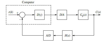
(a) Calculate both C (s) and C(z) for the system of Fig. P5.3-8. Note that C(s) cannot contain the
variable z.
(b) Note that the output functions in part (a) are identical to those found in Example 5.1, even though the two configurations are different. Explain why.
Example 5.1
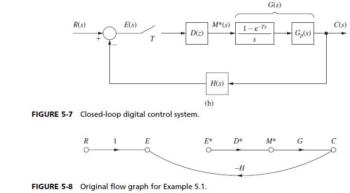
Consider the digital control system of Fig. 5-7(a) which has the model given in Fig. 5-7(b) (see
Section 4.4). The original flow graph is shown in Fig. 5-8.
We can write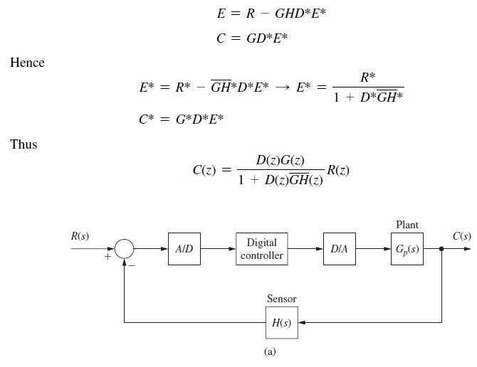
Step by Step Answer:
a R Gs 1 18T S G s C GM Cz M D R ...View the full answer


Digital Control System Analysis And Design
ISBN: 9780132938310
4th Edition
Authors: Charles Phillips, H. Nagle, Aranya Chakrabortty
