

Question: This problem is based on the solution in Problem 8.4-3. Suppose that in Fig. P8.4-3, the sensor gain (H=0.04) is moved back to the feedback
This problem is based on the solution in Problem 8.4-3. Suppose that in Fig. P8.4-3, the sensor gain \(H=0.04\) is moved back to the feedback path. What effect does this have on the percent steady-state error of Problem 8.4-3, where this error is defined as
\[
\text { steady-state error }=\frac{\text { commanded output }- \text { actual output }}{\text { commanded output }} \times 100
\]
Note that this result allows us to convert a nonunity feedback gain system to a unity-gain feedback system, without affecting the percentage steady-state error.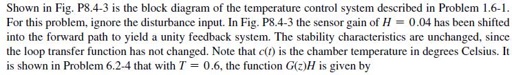
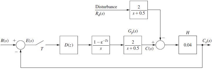
Problem 1.6-1![It is shown in [6] that given the partitioned matrix H DE F G where each partition is n Xn, the determinant](https://dsd5zvtm8ll6.cloudfront.net/images/question_images/1705/5/6/6/30465a8e0608f50a1705566303926.jpg)
Shown in Fig. P8.4-3 is the block diagram of the temperature control system described in Problem 1.6-1. For this problem, ignore the disturbance input. In Fig. P8.4-3 the sensor gain of H= 0.04 has been shifted into the forward path to yield a unity feedback system. The stability characteristics are unchanged, since the loop transfer function has not changed. Note that c(t) is the chamber temperature in degrees Celsius. It is shown in Problem 6.2-4 that with T = 0.6, the function G(z)H is given by
Step by Step Solution
3.36 Rating (168 Votes )
There are 3 Steps involved in it
Moving the sensor gain H004 back to the feedback path in the temperature control system described in ... View full answer

Get step-by-step solutions from verified subject matter experts