

Question: A Mealy sequential circuit is implemented using the circuit shown in Problem 1.26. Assume that if the input X changes, it changes at the same
(a) Complete the timing diagram shown here. Indicate the proper times to read the output (Z). Assume that €œdelay€ is 0 ns and that the propagation delay for the flip-flop and XOR gate has a nominal value of 10 ns. The clock period is 100 ns.
(b) Assume the following delays: XOR gate€”10 to 20 ns; flip-flop propagation delay€”5 to 10 ns; setup time€”5 ns; and hold time€”2 ns. Also assume that the €œdelay€ is 0 ns. Determine the maximum clock rate for proper synchronous operation. Consider both the feedback path that includes the flip-flop propagation delay and the path starting when X changes.
(c) Assume a clock period of 100 ns. Also assume the same timing parameters as in (b). What is the maximum value that €œdelay€ can have and still achieve proper synchronous operation? That is, the state sequence must be the same as for no delay.
Data from Problem 1.26
In the following circuit, the XOR gate has a delay in the range of 2 to 16 ns. The D flip-flop has a propagation delay from clock to Q in the range 12 to 24 ns. The setup
time is 8 ns, and the hold time is 4 ns.
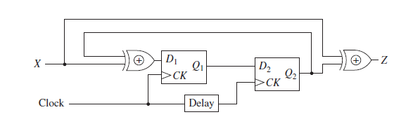
D1 Qi D2 Q2 >CK >CK Clock Delay
Step by Step Solution
★★★★★
3.47 Rating (170 Votes )
There are 3 Steps involved in it
1 Expert Approved Answer
Step: 1 Unlock

a Z should be read just before the rising edge of the clock b Worst case t xor t p t su t ... View full answer
Question Has Been Solved by an Expert!
Get step-by-step solutions from verified subject matter experts
Step: 2 Unlock
Step: 3 Unlock