

Question: A scan path test circuit of the type shown in Figure 10-8 has three flip-flops, two inputs, and two outputs. One row of the state
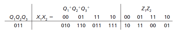
For this row of the table, complete a timing chart similar to that shown in Figure 10-9 to show how the circuit can be tested to verify the next states and outputs for inputs 00, 01, and 10. Show the expected Z1 and Z2 outputs only at the time when they should be read.
Q,*Q2*Q3 Z,Z, Q,Q,Q; | X,X, = 11 10 11 01 00 00 10 01 11 10 01 111 011 010 110 011 00
Step by Step Solution
★★★★★
3.30 Rating (159 Votes )
There are 3 Steps involved in it
1 Expert Approved Answer
Step: 1 Unlock

TCK I SCK 1 1 X1 X2 SDI SDO 1 I I 1 01 T 1 1 Z1 T 1 Z2 T T 1 T T 1 11 I XI 1 T T 1 1 1 T ... View full answer
Question Has Been Solved by an Expert!
Get step-by-step solutions from verified subject matter experts
Step: 2 Unlock
Step: 3 Unlock