

Question: Implement a 2-bit binary counter using one logic block as shown in Figure 6-1(a). A 0 is the least significant bit, and A 1 is
Implement a 2-bit binary counter using one logic block as shown in Figure 6-1(a). A0is the least significant bit, and A1is the most significant bit of the counter. The counter has a synchronous load (Ld). The counter operates as follows: En = 0 No change. En = 1, Ld = 1 Load A0and A1with external inputs U and V on rising edge of clock. En = 1, Ld = 0 Increment counter on rising edge of clock.
(a) Give the next-state equations for A0and A1.
(b) Show all required inputs and connections on a copy of Figure 6-1(a). Show the connection paths with heavy lines. Use the CE input. Give the function realized by each 4-input LUT.
Figure 6-1(a)
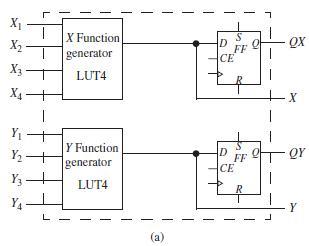
X X Function QX D FF CE X2 generator X - LUT4 X4- Y - Y Function generator to Y2 - D FF QY CE Y3 LUT4 YA Y L (a) L.
Step by Step Solution
3.49 Rating (162 Votes )
There are 3 Steps involved in it
a Q A0 En Ld U Ld Q A0 En Q A0 En X En Q A0 Q A1 En L... View full answer

Get step-by-step solutions from verified subject matter experts