

Question: Write a test bench for the elevator controller of Problem 5.10. The test bench has two functions: to simulate the operation of the elevator (including
To simulate the elevator: if the elevator is on the first floor (FS1= 1) and an UP signal is received, wait 1 second and turn off FS1; then wait 10 seconds and turn on FS2; this simulates the elevator moving from the first floor to the second. Similar action should occur if the elevator is on the second floor (FS2= 1) and a DOWN signal is received. When a door open signal is received (DO = 1), set door closed (DC) to 0, wait 5 seconds, and then set DC = 1.
Test sequence: CALL1, 2, FB2, 4, FB1, 1, CALL2, 10, FB2 Assume each button is held down for 1 second and then released. The numbers between buttons are the delays in seconds between button pushes; this delay is in addition to the 1 second the button is held down. Complete the following test bench:
module test_el;
.
.
.
elev_control eltest(CALL1, CALL2, FB1, FB2, FS1, FS2, DC, CLK,
UP, DOWN, DO);
.
.
.
.
endmodule
Data from Problem 5-10.
The block diagram for an elevator controller for a building with two floors is shown in the following diagram. The inputs FB1 and FB2 are floor buttons in the elevator. The inputs CALL1 and CALL2 are call buttons in the hall. The inputs FS1 and FS2 are floor switches that output a 1 when the elevator is at the first or second floor landing. Outputs UP and DOWN control the motor, and the elevator is stopped when UP = DOWN = 0. N1 and N2 are flip-flops that indicate when the elevator is needed on the first or second floor. R1 and R2 are signals that reset these flip-flops. DO = 1 causes the door to open, and DC = 1 indicates that the door is closed. Draw an SM chart for the elevator controller (four states).
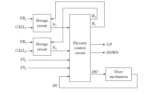
|R2 FB1 Storage R1 circuit N1 CALL, FB2 Elevator Storage N2 UP control circuit CALL2 circuit DOWN FS, FS2 | DO Door mechanism DC
Step by Step Solution
3.34 Rating (166 Votes )
There are 3 Steps involved in it
module testel reg CLK reg CALL1 CALL2 FB1 FB2 FS1 FS2 DC wire UP ... View full answer

Get step-by-step solutions from verified subject matter experts