New Semester
Started
Get
50% OFF
Study Help!
--h --m --s
Claim Now
Question Answers
Textbooks
Find textbooks, questions and answers
Oops, something went wrong!
Change your search query and then try again
S
Books
FREE
Study Help
Expert Questions
Accounting
General Management
Mathematics
Finance
Organizational Behaviour
Law
Physics
Operating System
Management Leadership
Sociology
Programming
Marketing
Database
Computer Network
Economics
Textbooks Solutions
Accounting
Managerial Accounting
Management Leadership
Cost Accounting
Statistics
Business Law
Corporate Finance
Finance
Economics
Auditing
Tutors
Online Tutors
Find a Tutor
Hire a Tutor
Become a Tutor
AI Tutor
AI Study Planner
NEW
Sell Books
Search
Search
Sign In
Register
study help
engineering
electronics fundamentals a systems approach
Electronics Fundamentals A Systems Approach 1st Edition Thomas Floyd - Solutions
What is the current through each of four resistors in a series circuit if the source voltage is 12 V and the total resistance is 120 Ω?
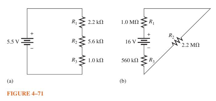
What is the current in each circuit of Figure 4–71? Show how to connect an ammeter in each case.Data in Figure 4–71 + 5.5v Ξ (2) FIGURE 4-71 R₁ R₂ R3 2.2 ΚΩ 5.6 ΚΩ 1.0 ΚΩ 1.0 ΜΩ 16 V 560 ΚΩ (b) R₁ + · R3, R₂ 2.2 ΜΩ
Determine the voltage across each resistor in Figure 4–71? 5.5 V (2) FIGURE 4-71 R₁ R₂ R₂ 2.2 ΚΩ 5.6 ΚΩ 1.0 ΚΩ 1.0 ΜΩ (b) 16V 7 Η 560 ΚΩ R₁ - R3, R₂ 2.2 ΜΩ
Three 470 Ω resistors are in series with a 48 V source. (a) How much current is there? (b) What is the voltage across each resistor? (c) What is the minimum power rating of the resistors?
Four equal-value resistors are in series with a 5 V source, and a current of 1 mA is measured. What is the value of each resistor?
What happens if one of the batteries in Problem 19 is accidentally connected in reverse?Data in Problem 19,Show how to connect four 6 V batteries to achieve a voltage of 24 V.
Determine the unspecified voltage drop(s) in each circuit of Figure 4–72. Show how to connect a voltmeter to measure each unknown voltage drop. 15 V (a) + + 2 V www 0.5 V www FIGURE 4-72 + V₂ - - 3.2 V www + 1 V 1.5 V www+ Vs (b) + + 8 V www R 4R ww R 3R www 2R
The following voltage drops are measured across each of three resistors in series: 5.5 V, 8.2 V, and 12.3 V. What is the value of the source voltage to which these resistors are connected?
Five resistors are in series with a 20 V source. The voltage drops across four of the resistors are 1.5 V, 5.5 V, 3 V, and 6 V. How much voltage is across the fifth resistor?
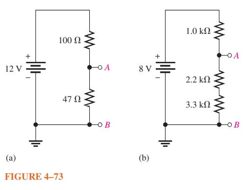
Find the voltage between A and B in each voltage divider of Figure 4–73. 12 V + | | 100 47 FIGURE 4-73 O B 8 V (b) + | 1.0 2.2 3.3 O B
The total resistance of a series circuit is 500 Ω. What percentage of the total voltage appears across a 22 Ω resistor in the series circuit?
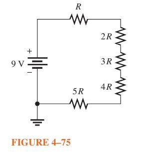
What is the voltage across each resistor in Figure 4–75? R is the lowest value and all others are multiples of that value as indicated. Data in Figure 4–75 + 9V= R M 5R www FIGURE 4-75 2R 3R 4R
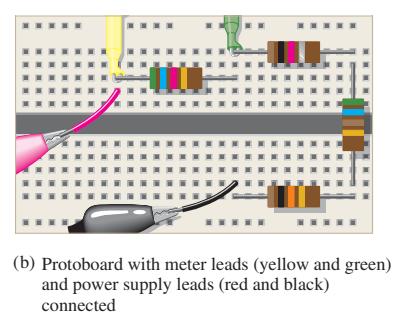
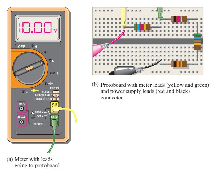
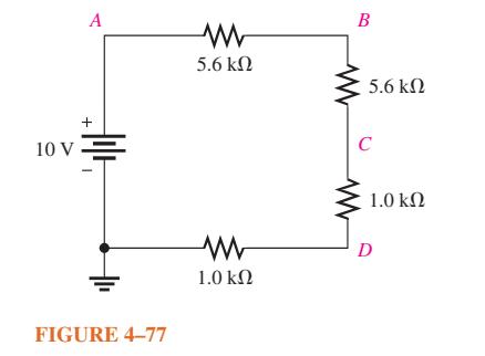
What is the voltage across each resistor on the protoboard in Figure 4–76 (b)? Data in Figure 4–76 (b), . . W W . **** 1 ***** (b) Protoboard with meter leads (yellow and green) and power supply leads (red and black) connected
Find the total power in Figure 4–76.Data in Figure 4–76 . 10.00 OFF 10 A O 40 mA Hz D+ A RANGE O AUTORANGE TOUCH/HOLD 1000 V... 750 V FUSED V mV H PRESS VO COM (a) Meter with leads going to protoboard * **** (b) Protoboard with meter leads (yellow and green) and power supply leads (red and
Five series resistors each dissipate 50 mW of power. What is the total power?
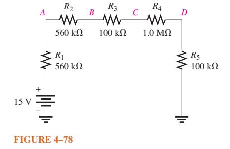
Determine the voltage at each point with respect to ground in Figure 4–77.Data in Figure 4–77 . A + 10 ν Ξ V FIGURE 4-77 5.6 ΚΩ 1.0 ΚΩ B 5.6 ΚΩ C 1.0 ΚΩ I D
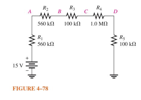
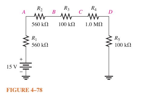
In Figure 4–78, how would you determine the voltage across R2 by measurement, without connecting a meter directly across the resistor?Data in Figure 4–78. 15 V A + R₂ 560 ΚΩ R₁ • 560 ΚΩ FIGURE 4-78 Β R3 Μ 100 ΚΩ C R4 Μ 1.0 ΜΩ D R5 100 ΚΩ
Determine the voltage at each point with respect to ground in Figure 4–78. 15 V A R₁ • 560 ΚΩ ΗΜΗ R₂ Μ 560 ΚΩ Ξ FIGURE 4-78 B R3 Μ 100 ΚΩ C R4 1.0 ΜΩ D R₁ 100 ΚΩ
In Figure 4–78, what is VAC? 15 V A Μ + R₁ • 560 ΚΩ R₂ Μ 560 ΚΩ Η FIGURE 4-78 B R3 100 ΚΩ C R4 Μ Μ 1.0 ΜΩ D CR5 100 ΚΩ
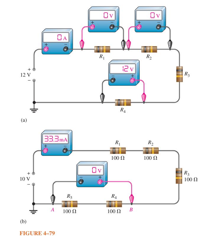
By observing the meters in Figure 4–79, determine the types of failures in the circuits and which components have failed. + 12 V (a) + 10 V (b) I +O 33.3mA A OA FIGURE 4-79 R5 100 Ω Ov Ri O+ R₁ 100 Ω R4 100 Ω 12v R₁ O+< B Ov V R₂ R₂ 100 Ω R3 R3 100 Ω
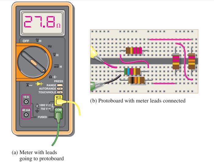
Is the multimeter reading in Figure 4–80 correct? If not, what is wrong? Data in Figure 4–80 27.8. OFF A 10 A 40 mA 1000 V Hz FUSED VH 750 V~ mV H 2+ RANGE AUTORANGE C TOUCH/HOLD PRESS VO COM (a) Meter with leads going to protoboard IT ***** www. (b) Protoboard with meter leads connected
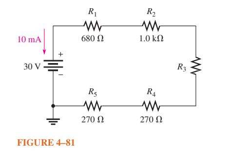
Determine the unknown resistance (R3) in the circuit of Figure 4–81.Data in Figure 4–81. 10 mA 30 V + FIGURE 4-81 R₁ Μ 680 Ω R5 Μ 270 Ω R₂ Μ 1.0 ΚΩ R4 270 Ω R3
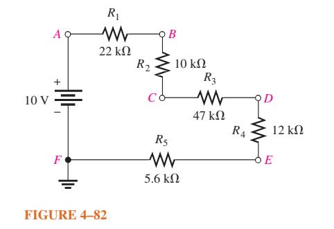
Determine the voltage at each point in Figure 4–82 with respect to ground. Data in Figure 4–82. 10 V A + F R 22 FIGURE 4-82 R B 10 R 5.6 R3 47 R D 12
Develop a variable voltage divider to provide output voltages ranging from a minimum of 10 V to a maximum of 100 V using a 120 V source. The maximum voltage must be at the maximum resistance setting of the potentiometer. The minimum voltage must be at the minimum resistance (zero ohms) setting. The
A certain series circuit is made up of a 1/8 W resistor, a 1/4 W resistor, and a 1/2 W resistor. The total resistance is 2400. If each of the resistors is operating at its maximum power level, determine the following:(a) I(b) VS (c) The value of each resistor.
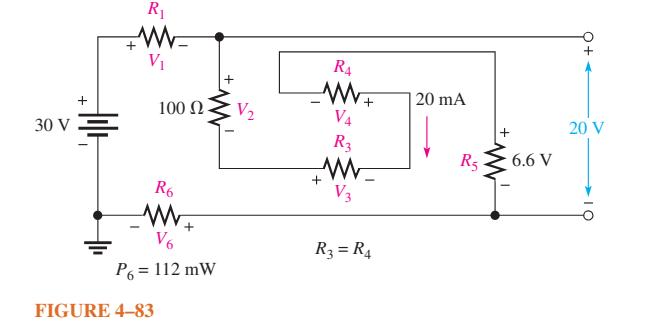
Find all the unknown quantities (shown in red) in Figure 4–83.Data in Figure 4–83. 30 V + R₁ WW V₁ 100 (2 R6 www. V6 P6 = 112 mW FIGURE 4-83 V₂ R4 W+ + V4 R3 www. V3 + R3 = R4 20 mA R5 + 6.6 V 20 V
Assume the trailer in Problem 18 has two brake lights that draw 1 A each.Data in Problem 18A trailer has four running lights that draw 0.5 A each and two taillights that draw 1.2 A each. What is the current supplied to the trailer when the taillights and running lights are on?
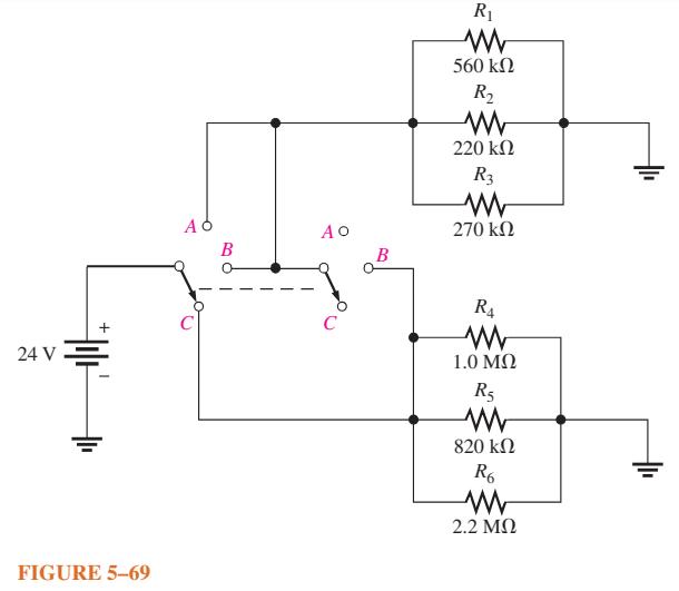
Determine the total current from the source and the current through each resistor for each switch position in Figure 5–69. 24 V III. FIGURE 5-69 ΑΦ B ΑΟ B R₁ Μ 560 ΚΩ R₂ Μ 220 ΚΩ R3 Μ 270 ΚΩ R₁ 1.0 ΜΩ R₁ Μ 820 ΚΩ R6 2.2 ΜΩ
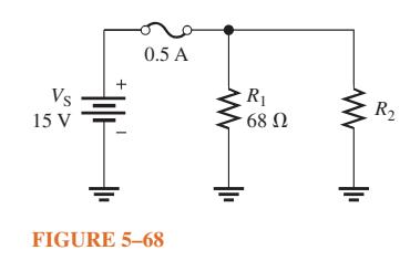
What value of R2 in Figure 5–68 will cause excessive current? Vs 15 V + .. 0.5 A FIGURE 5-68 www R₁ 68 Ω R₂
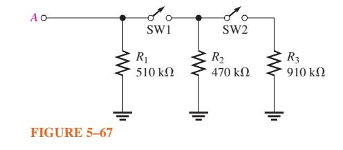
What is the total resistance between terminal A and ground in Figure 5–67 for the following conditions?(a) SW1 and SW2 open (b) SW1 closed, SW2 open (c) SW1 open, SW2 closed (d) SW1 and SW2 closed. ΑΟ FIGURE 5-67 SW1 R₁ 510 ΚΩ SW2 R₂ 470 ΚΩ R3 910 ΚΩ
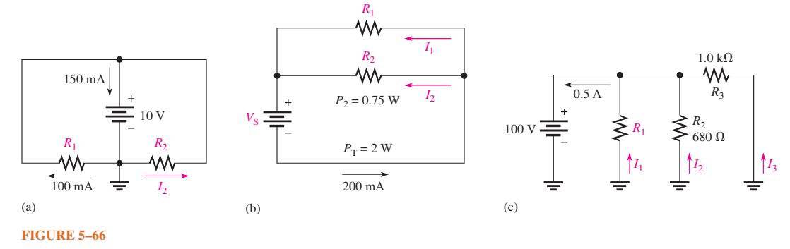
Find the values of the unspecified quantities (shown in color) in each circuit of Figure 5–66. (a) 150 mA R₁ 100 mA FIGURE 5-66 = 10 V R₂ www 12 (b) R₁ R₂ www P₂ = 0.75 W PT = 2 W 200 mA 1₁ 1₂ 100 V (c) 0.5 A R₁ 1.0 ΚΩ www R3 R₂ 680 Ω
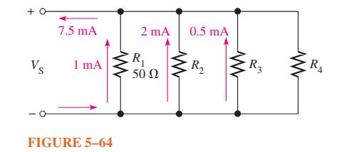
In the circuit of Figure 5–64, determine resistances R2, R3, and R4.Data in Figure 5–64 +0 Vs 7.5 mA 1 mA FIGURE 5-64 2 mA R₁ 50 Ω 0.5 mA R₂ www R3 R4
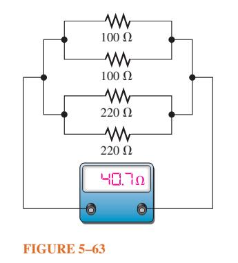
From the ohmmeter reading in Figure 5–63, can you tell if a resistor is open? If so, can you identify it? Μ 100 Ω Μ 100 Ω Μ 220 Ω Μ 220 Ω ΗΠΤΩ FIGURE 5-63
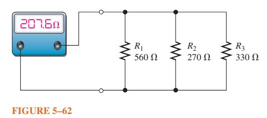
Find the open resistor in Figure 5–62. ΞΕΤΕΩ FIGURE 5-62 Μ CR₁ 560 Ω R₂ 270 Ω Μ R3 330 Ω
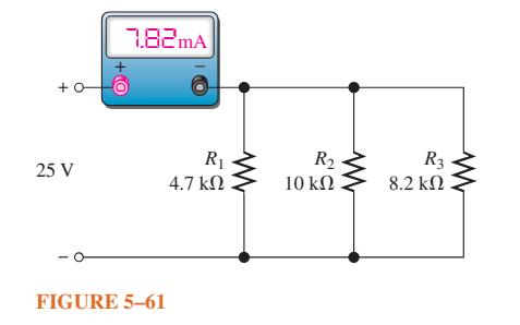
What is wrong with the circuit in Figure 5–61? +0 25 V 7.82mA FIGURE 5-61 R₁ 4.7 ΚΩ R₂ 10 ΚΩ R3 8.2 ΚΩ
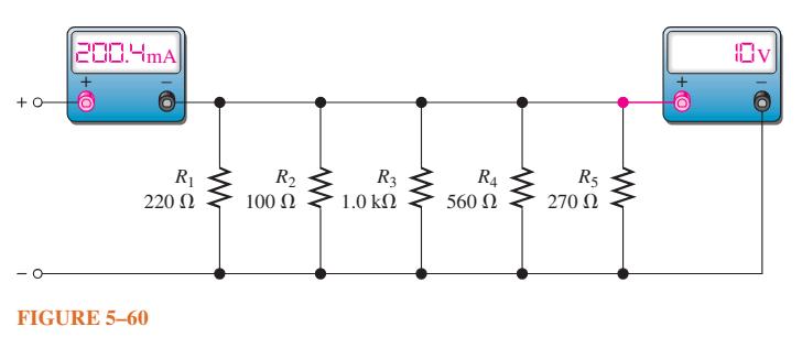
In Figure 5–60, the current and voltage measurements are indicated. Has a resistor opened, and, if so, which one? +0 200.4mA R₁ 220 Ω FIGURE 5-60 R₂ 100 Ω R3 1.0 ΚΩ R4 560 Ω R5 270 Ω +O 10v
Six light bulbs are connected in parallel across 120 V. Each bulb is rated at 75 W. How much current is through each bulb, and what is the total current?
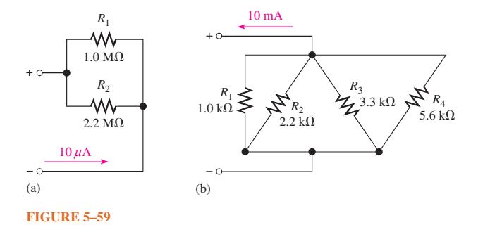
Using the current-divider formula, determine the current in each branch of the circuits of Figure 5–59. Data in Figure 5–59 . +0 (2) R₁ 1.0 ΜΩ R₂ Μ 2.2 ΜΩ 10 Α FIGURE 5-59 +0 R₁ 1.0 ΚΩ (b) 10 mA www R₂ 2.2 ΚΩ Μ R₂ 3.3 ΚΩ R₁ 5.6 ΚΩ
Five parallel resistors each handle 40 mW. What is the total power?
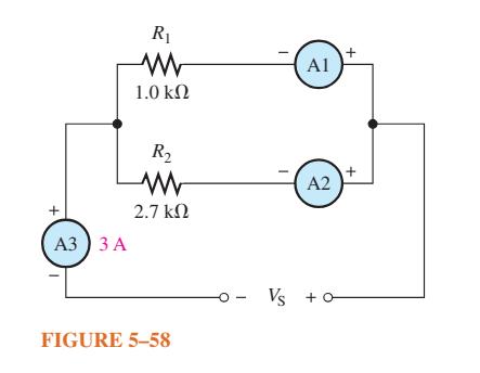
How much branch current should each meter in Figure 5–58 indicate? + A3 ) 3 A R₁ 1.0 ΚΩ R₂ 2.7 ΚΩ FIGURE 5-58 - Vs Al Α2 +0 + +
A 10 kΩ resistor and a 15 kΩ resistor are in parallel with a voltage source. Which resistor has the highest current?
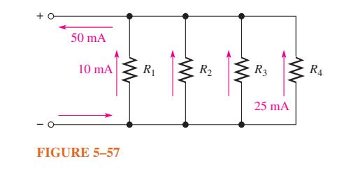
How much current is through R2 and R3 in Figure 5–57 if R2 and R3 have the same resistance? Show how to connect ammeters to measure these currents.Data in Figure 5–57 +0 50 mA 10 mA FIGURE 5-57 www R₁ R₂ R3 www 25 mA R4
A trailer has four running lights that draw 0.5 A each and two taillights that draw 1.2 A each. What is the current supplied to the trailer when the taillights and running lights are on?
There is a total of 500 mA of current into five parallel resistors. The currents through four of the resistors are 50 mA, 150 mA, 25 mA, and 100 mA. What is the current through the fifth resistor?
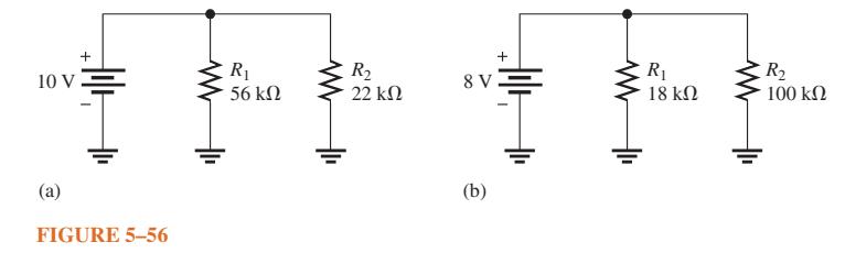
What is the current in each resistor for the circuits shown in Figure 5–56? + (2) Alli 10 V . FIGURE 5-56 Μ R₁ 56 ΚΩ R₂ 22 ΚΩ 8 V (b) + Alli | R₁ 18 ΚΩ R₂ 100 ΚΩ
The following currents are measured in the same direction in a three-branch parallel circuit: 250 mA, 300 mA, and 800 mA. What is the value of the current into the node to which these three branches are connected?
Four equal-value resistors are connected in parallel. Five volts are applied across the parallel circuit, and 2.5 mA are measured from the source. What is the value of each resistor?
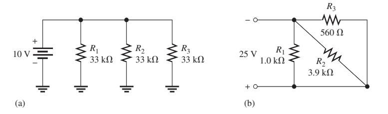
What is the total current, IT, in each circuit of Figure 5–55?Data in Figure 5–55 + 10v = (a) R R R3 33 kl) 33 kQ 33 kQ 25 V + (b) R 1.0 k2 R3 560 2 R 3.9 kQ
The source voltage in Figure 5–54 is 100 V. How much voltage does each of the three meters read? + 100 V V1 FIGURE 5-54 R₁ www R₂ + V2 R3 V3
The resistance of a 60 W bulb is approximately 240 Ω. What is the current from the source when three bulbs are on in a 120 V parallel circuit?
Determine the voltage across and the current through each parallel resistor if the total voltage is 12 V and the total resistance is 600 Ω. There are four resistors, all of equal value.
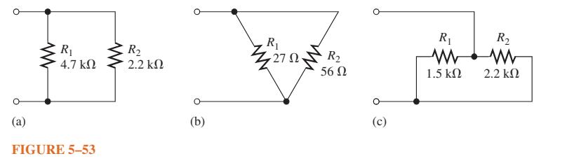
Calculate RT for each circuit in Figure 5–53. (2) R 4.7 FIGURE 5-53 R 2.2 (b) R 27 R 56 (c) R 1.5 R 2.2
Find the total resistance between nodes A and B for each group of parallel resistors in Figure 5–52. Data in Figure 5–52. A (a) (TO) B A (b) FICH B
What is the total resistance of eleven 22 kΩ resistors in parallel?
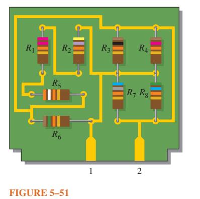
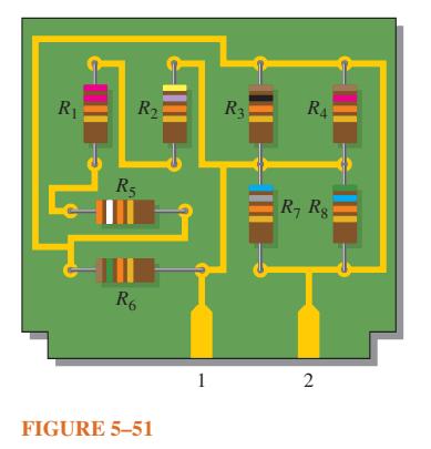
Determine the total resistance between pins 1 and 2 in Figure 5–51. R R R5 R6 FIGURE 5-51 1 R3 R4 R7 R8 2
Determine whether or not all the resistors in Figure 5–51 are connected in parallel on the printed circuit board. Draw the schematic including resistor values. R R I R R6 FIGURE 5-51 1 R3 R4 R7 R8 2
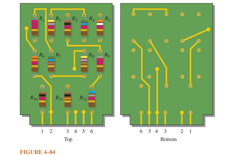
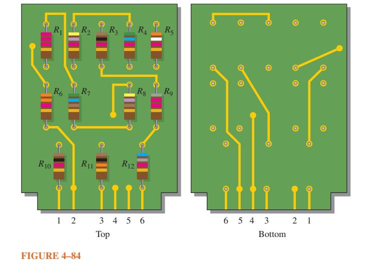
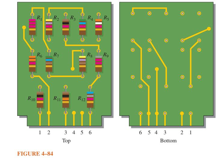
The three groups of series resistors on the PC board in Figure 4–84 are connected in series with each other to form a single series circuit by connecting pin 2 to pin 4 and pin 3 to pin 5. A voltage source is connected across pins 1 and 6 and an ammeter is placed in series. As you increase the
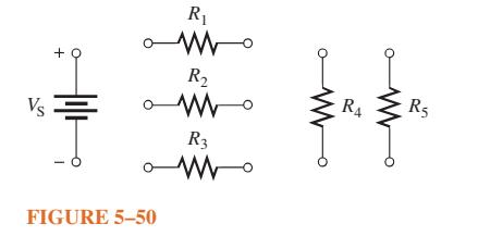
Connect the resistors in Figure 5–50 in parallel across the battery. Vs + FIGURE 5-50 R www R www R3 www R R5
You measure 15 kΩ between pins 5 and 6 on the PC board in Figure 4–84. Does this indicate a problem? If so, identify it. Data in Figure 4–84. R10 R R6 b 12 R R R3 R FIGURE 4-84 R1 T R12 Top R Rg 3456 R5 R9 O O O TO 6543 Bottom O 21 O O
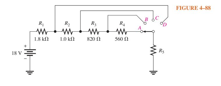
Determine the voltage across each resistor in Figure 4–88 for each switch position if the current through R5 is 6 mA when the switch is in the D position. 18 V R₁ 1.8 ΚΩ Ξ R₂ Μ 1.0 ΚΩ ΓΙ R3 Μ 820 Ω R4 560 Ω B R5 FIGURE 4-88
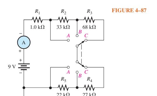
Determine the current measured by the meter in Figure 4–87 for each position of the ganged switch. 9V A Ar R₁ 1.0 ΚΩ R₂ Μ 33 ΚΩ A A R5 210 B R3 www 68 ΚΩ C C R4 27kQ FIGURE 4-87
Determine the current measured by the meter in Figure 4–86 for each switch position.Data in Figure 4–86. 12 V + i|r R₁ Μ 220 Ω A R₂ Μ 470 Ω B D A + R3 510 Ω R4 1.0 ΚΩ FIGURE 4-86
What is the total resistance from A to B for each switch position in Figure 4–85.Data in Figure 4–85. R₁ Ao W 510 Ω R5 BO W ΒΟ 680 Ω R₂ 910 Ω οι 62 16 20 Μ R3 Μ 820 Ω R4 750 Ω FIGURE 4-85
On the double-sided PC board in Figure 4–84, identify each group of series resistors and determine its total resistance. Note that many of the interconnections feed through the board from the top side to the bottom side.Data in Figure 4–84. R10 R₁ R6 b 12 R₂ R3 R4 R5 R₁ R₁1 FIGURE
The electrical circuit in a room is protected with a 15 A circuit breaker. A space heater that draws 8.0 A is plugged into one wall outlet, and two table lamps that draw 0.833 A each are plugged into another outlet. Can a vacuum cleaner that uses 5.0 A be plugged into this same circuit without
If one of the bulbs burns out in Problem 25, how much current will be through each of the remaining bulbs? What will be the total current?Data in Problem 25Six light bulbs are connected in parallel across 120 V. Each bulb is rated at 75 W. How much current is through each bulb, and what is the
The total resistance of a parallel circuit is 25 Ω. What is the current through a 220 Ω resistor that makes up part of the parallel circuit if the total current is 100 mA?
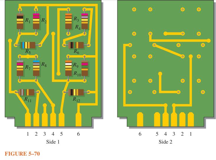
Identify which groups of resistors are in parallel on the double-sided PC board in Figure 5–70. Determine the total resistance of each group. R₁ R5 R₁ R11 R₂ FIGURE 5-70 Rg 12345 Side 1 R3 RA R6 Rg R10 R12 6 6 1/ L 54321 Side 2
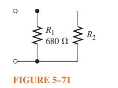
If the total resistance in Figure 5–71 is 200 Ω, what is the value of R2? R₁ 680 Ω FIGURE 5-71 R₂
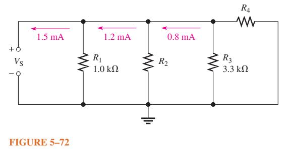
Determine the unknown resistances in Figure 5–72. + Vs 1.5 mA FIGURE 5-72 1.2 mA R₁ 1.0 ΚΩ 0.8 mA R₂ R4 R₂ 3.3 ΚΩ
There is a total of 250 mA into a parallel circuit with a total resistance of 1.5 k Ω. The current must be increased by 25%. Determine how much resistance to add in parallel to accomplish this increase in current.
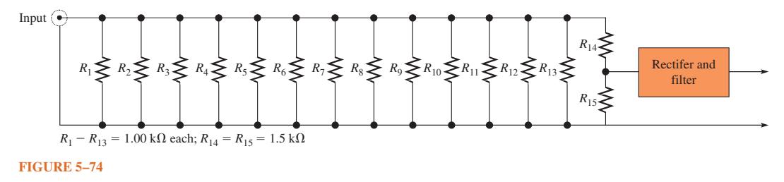
A dummy load has the values shown in Figure 5–74. All resistors are rated for 2 W except R14 and R15 are rated for 1/2 W each. (a) What is the resistance of the load? (b) What is its power rating? Input R₁ R₂ R3 R4 R5 R6 R73 www R₁ R13 1.00 kn each; R14 = R15 = 1.5 k FIGURE
A certain circuit is composed of two parallel resistors. The total resistance is 667 Ω. One of the resistors is 1.0 kΩ. What is the other resistor?
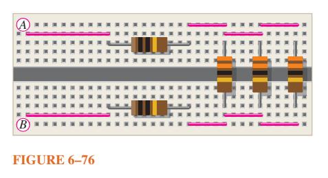
For the circuit in Figure 6–76, determine the total resistance between A and B. A (B) = FIGURE 6-76
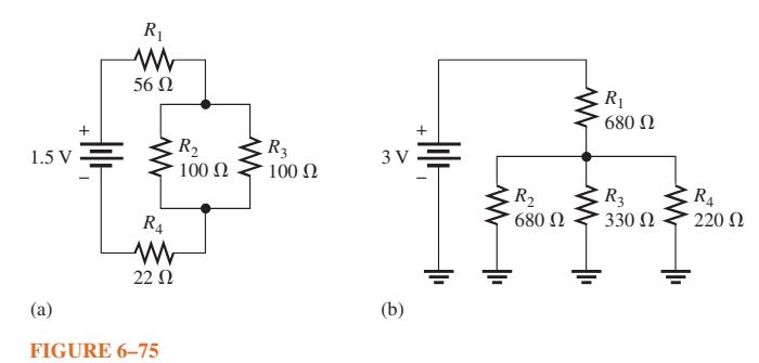
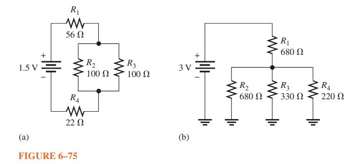
Determine the total resistance for each circuit in Figure 6–75. 1.5V (a) Ar 1 R₁ 56 Ω R4 Μ 22 Ω FIGURE 6-75 R₂ 100 Ω CR₂ 100 Ω 3v Ξ (b) R₂ 680 Ω R₁ 680 Ω R3 330 Ω R₁ 220 Ω
The total resistance of a parallel circuit is 25 Ω . If the total current is 100 mA, how much current is through a 220 Ω resistor that makes up part of the parallel circuit?
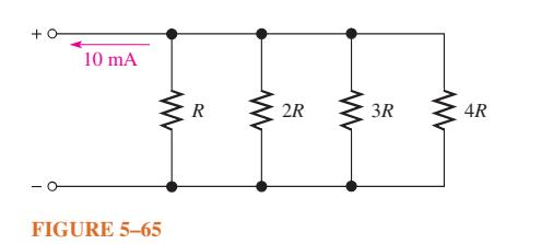
What is the current through each resistor in Figure 5–65? R is the lowest-value resistor, and all others are multiples of that value as indicated. +0 10 mA www FIGURE 5-65 R www 2R 3R 4R
Visualize and draw the following series-parallel combinations: (a) R1 in series with the parallel combination of R2 and R3. (b) R1 in parallel with the series combination of R2 and R3. (c) R1 in parallel with a branch containing R2 in series with a parallel combination of four other
Visualize and draw the following series-parallel circuits: (a) A parallel combination of three branches, each containing two series resistors. (b) A series combination of three parallel circuits, each containing two parallel resistors.
In each circuit of Figure 6–75 identify the series and parallel relationships of the resistors viewed from the source.Data in Figure 6–75. + 1.5v Ξ (2) 1 R₁ Μ 56 Ω R₁ 22 Ω FIGURE 6-75 R₂ 100 Ω R3 100 Ω 3V (b) Hilt | | Μ R₂ 680 Ω Μ R₁ 680 Ω R3 330 Ω < R4 220 Ω
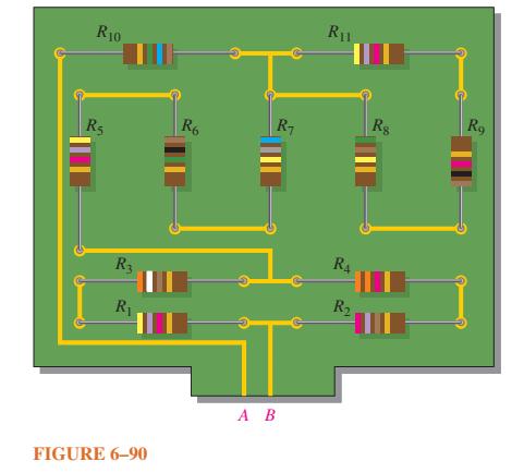
Draw the schematic of the PC board layout in Figure 6–90 showing resistor values and identify the series-parallel relationships. Which resistors, if any, can be removed with no effect on RT?Data in Figure 6–90 R10 R5 R3 R FIGURE 6-90 R6 R iT A B R1 R4 R Rs Ro
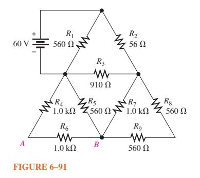
For the circuit shown in Figure 6–91, calculate the following:(a) Total resistance across the source (b) Total current from the source (c) Current through the 910 resistor (d) Voltage from point A to point B 60 V A R₁ 560 Ω R₁ 1.0 ΚΩ R6 Μ 1.0 ΚΩ FIGURE
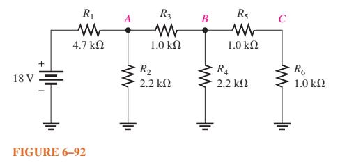
Determine the total resistance and the voltage at points A, B, and C in the circuit of Figure 6–92. 18 V + 놓 R₁ Μ 4.7 ΚΩ FIGURE 6-92 R3 Μ 1.0 ΚΩ R₂ 2.2 ΚΩ B Μ R5 Μ 1.0 ΚΩ RA 2.2 ΚΩ C R6 1.0 ΚΩ
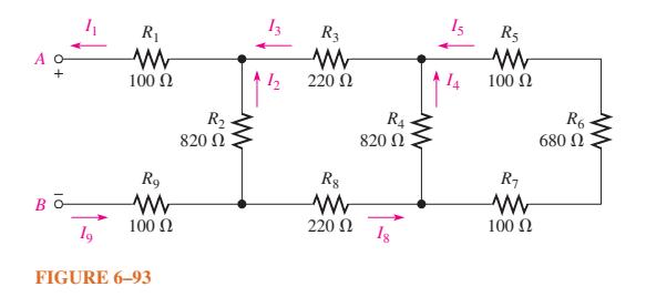
Determine the total resistance between terminals A and B of the circuit in Figure 6–93 . Also calculate the current in each branch with 10 V between A and B. Βα 19 R₁ Μ 100 Ω Rg Μ 100 Ω FIGURE 6-93 R₂ 820 Ω I 1 R3 Μ 220 Ω R8 Μ 220 Ω R₁ 820 Ω 18 R5 Μ 100 Ω R₁ Μ 100 Ω R6 680
What is the voltage across each resistor in Figure 6–93 ? There are 10 V between A and B. + ΒΟ lg R₁ Μ 100 Ω Ry 100 Ω FIGURE 6-93 R₂ 820 Ω Μ 13 1 R3 Μ 220 Ω R8 Μ 220 Ω R4 Μ 820 Ω Is R5 Μ 100 Ω R₁ 100 Ω R6 680 Ω
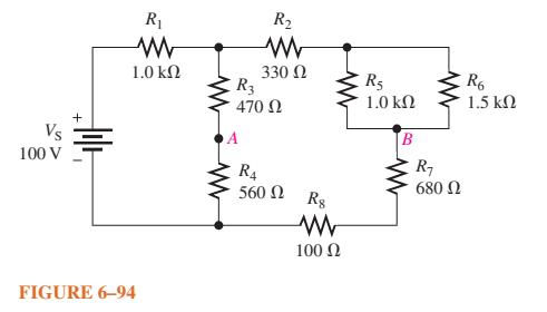
Determine the voltage, VAB, in Figure 6–94. Vs 100 V + Hilt R₁ Μ 1.0 ΚΩ FIGURE 6-94 R₂ ΜΕ 330 Ω R3 470 Ω R4 560 Ω Rg Μ 100 Ω R5 1.0 ΚΩ B R₁ 680 Ω R6 1.5 ΚΩ
Find the value of R2 in Figure 6–95. Vs 220 V + FIGURE 6-95 R₁ www 47 ΚΩ R₂ www 1 mA R3 33 ΚΩ www
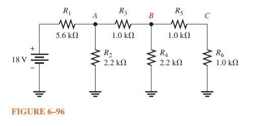
Determine the total resistance and the voltage at points A , B , and C in the circuit of Figure 6–96. 18 V R₁ Μ 5.6 ΚΩ FIGURE 6-96 Μ R3 Μ 1.0 ΚΩ R₂ 2.2 ΚΩ B R5 Μ 1.0 ΚΩ R₁ 2.2 ΚΩ R6 1.0 ΚΩ
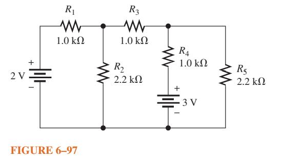
Using the superposition theorem, calculate the current in the right-most branch of Figure 6–97. + 2v Ξ R₁ Μ 1.0 ΚΩ FIGURE 6-97 R3 Μ 1.0 ΚΩ R₂ 2.2 ΚΩ R₁ 1.0 ΚΩ 3V ww R5 2.2 ΚΩ
Develop a voltage divider to provide a 6 V output with no load and a minimum of 5.5 V across a 1.0 kΩ load. The source voltage is 24 V, and the unloaded current is not to exceed 100 mA.
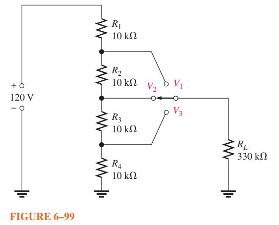
The voltage divider in Figure 6–99 has a switched load. Determine the voltage at each tap (V1, V2, and V3) for each position of the switch. + 120 V FIGURE 6-99 www R₁ 10 ΚΩ R₂ 10 ΚΩ R3 10 ΚΩ R4 10 ΚΩ V₂ 8 V₁ V3 RL 330 ΚΩ
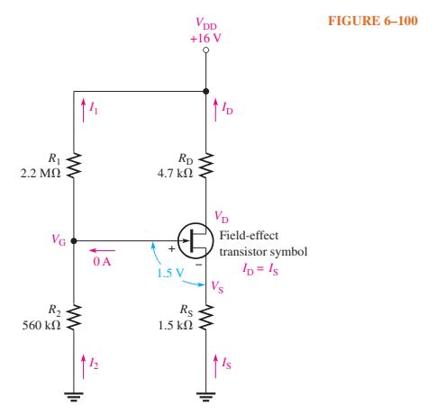
Figure 6–100 shows a dc biasing arrangement for a field-effect transistor amplifier. Biasing is a common method for setting up certain dc voltage levels required for proper amplifier operation. Although you may not be familiar with transistor amplifiers at this point, the dc voltages and currents
For the circuit in Figure 6–100 , what is VG if R1 is open? R₁ 2.2 ΜΩ VG R₂ www 560 ΚΩ OA 4.7 ΚΩ RD + VDD +16 V 1.5 V 11D (H) Rs 1.5 ΚΩ www VD www Field-effect transistor symbol ID = Is FIGURE 6-100
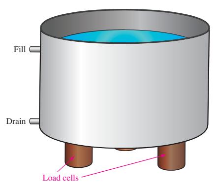
For the liquid-level sensing system in Figure 6–40, what is the advantage of using three load cells over four? Data in Figure 6–40. Fill Drain Load cells
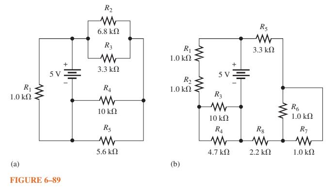
In each circuit of Figure 6–89, identify the series and parallel relationships of the resistors viewed from the source. R 1.0 + (a) FIGURE 6-89 sv Alli | R 6.8 R3 3.3 R4 10 R5 5.6 R 1.0 R 1.0 (b) WW + 5V = R3 10 R 4.7 R5 3.3 R8 2.2 R6 1.0 R 1.0
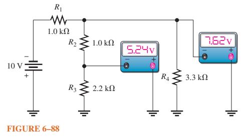
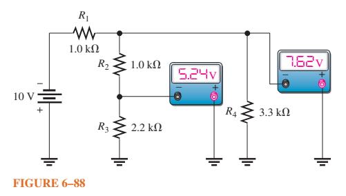
Determine the voltage you would expect to measure across each resistor in Figure 6–88 for each of the following faults: (a) R1 open (b) R2 open (c) R3 open (d) A short across R4 10 v Ξ + R₁ Μ 1.0 ΚΩ FIGURE 6-88 R₂ R3 Μ 1.0 ΚΩ 2.2 ΚΩ Εξήν RA 3.3 ΚΩ ΤΕΞv
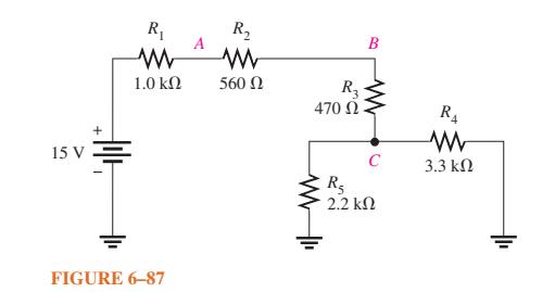
Determine the voltage you would expect to measure across each resistor in Figure 6–87 for each of the following faults. Assume the faults are independent of each other.(a) R1 open (b) R3 open (c) R4 open (d) R5 open (e) Point C shorted to ground. 15 V R₁ 1.0 ΚΩ FIGURE
If R2 in Figure 6–87 opens, what voltages will be read at points A, B, and C? 15 V + R₁ Μ 1.0 ΚΩ FIGURE 6–87 A R₂ Μ 560 Ω R3 470 Ω Β C R₂ 2.2 ΚΩ R₁ Μ 3.3 ΚΩ
Check the meter readings in Figure 6–88 and locate any fault that may exist. 10 V + R₁ Μ 1.0 ΚΩ FIGURE 6–88 R₂ R3 1.0 ΚΩ 2.2 ΚΩ 5.040 R4 Tδεν 3.3 ΚΩ
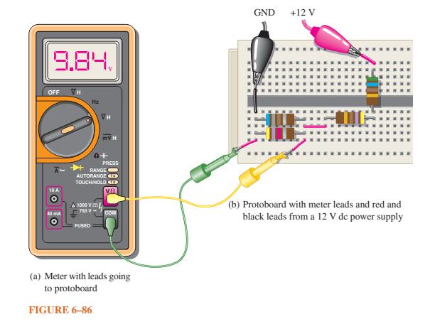
Is the voltmeter reading in Figure 6–86 correct? If not, what is the problem? 9.84. OFF 10 A 40 mA H RANGE AUTORANGE TOUCH/HOLD 1000 V 750 V = FUSED PRESS VS COM (a) Meter with leads going to protoboard FIGURE 6-86 GND +12 V (b) Protoboard with meter leads and red and black leads from a 12
Showing 400 - 500
of 641
1
2
3
4
5
6
7
Step by Step Answers