New Semester
Started
Get
50% OFF
Study Help!
--h --m --s
Claim Now
Question Answers
Textbooks
Find textbooks, questions and answers
Oops, something went wrong!
Change your search query and then try again
S
Books
FREE
Study Help
Expert Questions
Accounting
General Management
Mathematics
Finance
Organizational Behaviour
Law
Physics
Operating System
Management Leadership
Sociology
Programming
Marketing
Database
Computer Network
Economics
Textbooks Solutions
Accounting
Managerial Accounting
Management Leadership
Cost Accounting
Statistics
Business Law
Corporate Finance
Finance
Economics
Auditing
Tutors
Online Tutors
Find a Tutor
Hire a Tutor
Become a Tutor
AI Tutor
AI Study Planner
NEW
Sell Books
Search
Search
Sign In
Register
study help
engineering
electronics fundamentals a systems approach
Electronics Fundamentals A Systems Approach 1st Edition Thomas Floyd - Solutions
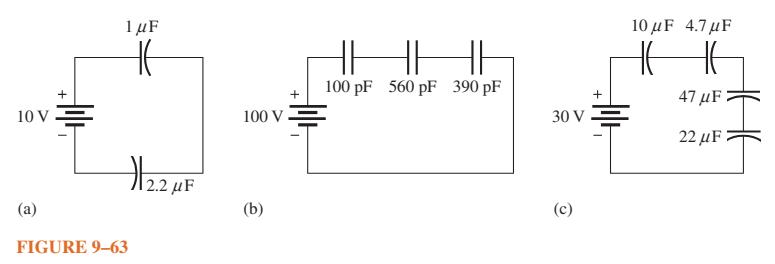
Find the total capacitance for each circuit in Figure 9–63. 10 V (a) + L 1 μF FIGURE 9-63 2.2 μF 100 V (b) + HH 100 pF 560 pF 390 pF 30 V (c) + 10 μF 4.7 μF H HE 47μF 22 μF
Name two types of electrolytic capacitors. How do electrolytics differ from other capacitors?
For each circuit in Figure 9–63, determine the voltage across each capacitor. + 10 V. (a) 1 μF HE FIGURE 9-63 2.2 μF 100 V (b) + HH 100 pF 560 pF 390 pF 30 V (c) + 10 μF 4.7μF HEE H 47 μF 22 μF
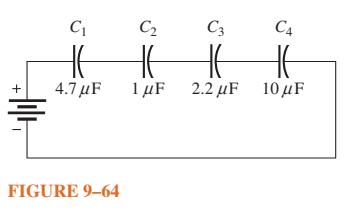
The total charge stored by the series capacitors in Figure 9–64 is 10 μC. Determine the voltage across each of the capacitors. + C₁ HE 4.7μF FIGURE 9-64 C₂ C3 C4 HE HE HE 1μF 2.2 μF 10 μF
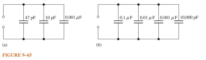
Determine CT for each circuit in Figure 9–65. (a) 47 pF FIGURE 9-65 10 pF 0.001 μF (b) 0.1 μF 0.01 μF 0.001 μF 10,000 pF T
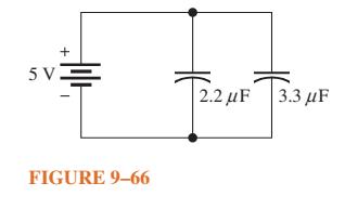
Determine the total capacitance and total charge on the capacitors in Figure 9–66. 5 V FIGURE 9-66 2.2 μF 3.3 μF
Determine the time constant for each of the following series RC combinations: (a) R = 100 , C = 1 μF (c) R = 4.7 kN, C = 0.0047μF (b) R = 10 MQ, C = 56 pF (d) R = 1.5 M2, C = 0.01 μF
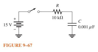
In the circuit of Figure 9–67, the capacitor initially is uncharged. Determine the capacitor voltage at the following times after the switch is closed: 15 V + FIGURE 9-67 R Μ 10 ΚΩ C 0.001 με
Determine how long it takes the capacitor to reach full charge for each of the following combinations: (a) R = 47 2, C = 47μF (c) R = 22 kn, C = 100 pF (b) R 3300 , C = 0.015 μF (d R = 4.7 MQ, C = 10 pF
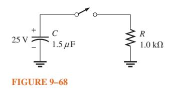
In Figure 9–68, the capacitor is charged to 25 V. Find the capacitor voltage at the following times when the switch is closed: 25 V + C 1.5 με FIGURE 9-68 R 1.0 ΚΩ
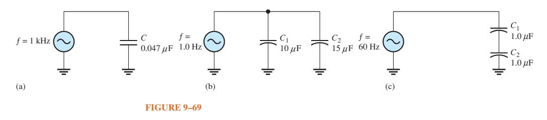
What is the value of the total capacitive reactance in each circuit in Figure 9–69? f = 1 kHz (~ (a) C f= 0.047|F 1.0Hz FIGURE 9-69 )b( ܘܙܕܝ [ C₁ 10 uF C f= 15F 60 Hz (c) ( C₁ 10IF C2 1.0 uF
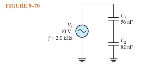
For the circuit in Figure 9–70, find the reactance of each capacitor, the total reactance, and the voltage across each capacitor. FIGURE 9-70 Vs 10 V f = 2.0 kHz O C₁ 56 nF C₂ 82 nF
A sinusoidal voltage of 20 V rms produces an rms current of 100 mA when connected to a certain capacitor. What is the reactance?
A 10 kHz voltage is applied to a 0.0047 μF capacitor, and 1 mA of rms current is measured. What is the rms value of the voltage?
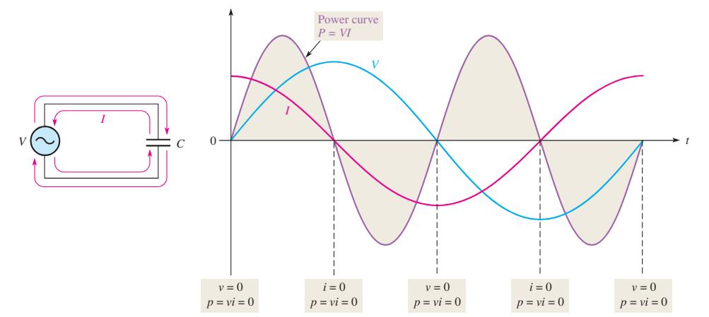
If another capacitor is connected in parallel with the existing capacitor in the power supply filter of Figure 9–52, how is the ripple voltage affected?Data in Figure 9–52 с v=0 p=vi = 0 Power curve P = VI i=0 p=vi = 0 v = 0 p=vi = 0 i=0 p=vi = 0 v=0 p=vi=0
Determine the true power and the reactive power in Problem 36. Data in Problem 36.A 10 kHz voltage is applied to a 0.0047 μF capacitor, and 1 mA of rms current is measured. What is the rms value of the voltage?
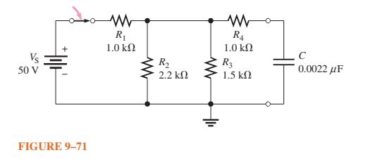
Determine the time constant for the circuit in Figure 9–71. Vs 50 V tr FIGURE 9-71 Μ R₁ 1.0 ΚΩ Μ R₂ 2.2 ΚΩ Μ R₁ 1.0 ΚΩ R3 1.5 ΚΩ C 0.0022 με
Ideally, what should the reactance of a bypass capacitor be in order to eliminate a 10 kHz ac voltage at a given point in an amplifier circuit?
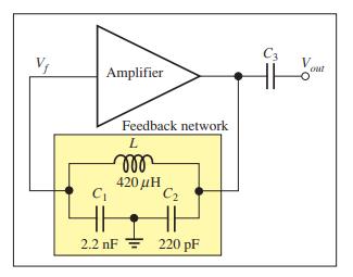
For the Colpitts oscillator in Figure 9–23, assume you need to change C1 to obtain a feedback fraction of 15%. What value would you select?Data in Figure 9–23, Amplifier Feedback network L m 420 ΜΗ C₁ C₂ 2.2 nF 220 pF C3 Vout
A square wave has a period of 40 μs. List the first six odd harmonics.
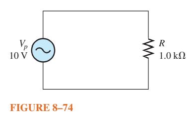
A sinusoidal voltage is applied to the resistive circuit in Figure 8–74. Determine the following: (a) Irms (b) Iavg (c) Ip (d) Ipp (e) I at the positive peak. 10 V FIGURE 8-74 R 1.0 ΚΩ
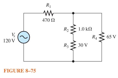
Find the half-cycle average values of the voltages across R1 and R2 in Figure 8–75. All values shown are rms. V₂ 120 V FIGURE 8-75 R₁ 470 02 R₂ R3 1.0 ΚΩ 30 V R4 65 V
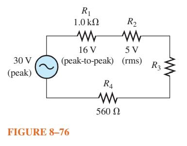
Determine the rms voltage across R3 in Figure 8–76. 30 V (peak) R₁ 1.0 ΚΩ W 16 V (peak-to-peak) FIGURE 8-76 R4 560 Ω R₂ 5 V (rms) R3 ww
A sine wave with an rms value of 10.6 V is riding on a dc level of 24 V. What are the maximum and minimum values of the resulting wave form?
How much dc voltage must be added to a 3 V rms sine wave in order to make the resulting voltage non alternating (no negative values)?
At what speed of rotation must a four-pole generator be operated to produce a 400 Hz sinusoidal voltage?
A common frequency for alternators on aircraft is 400 Hz. How many poles does a 400 Hz alternator have if the speed of rotation is 3000 rpm?
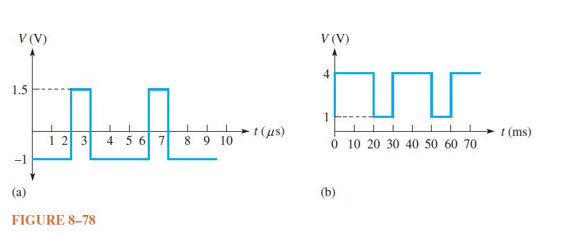
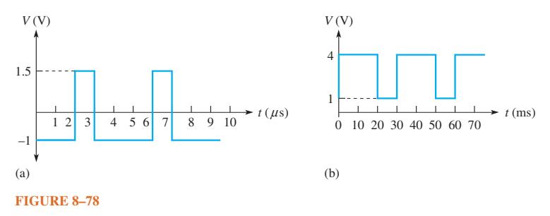
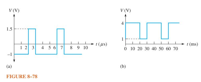
Determine the duty cycle for each pulse waveform in Figure 8–78. V(V) 1.5 -1 1 2 3 FIGURE 8-78 4 5 6 7 8 9 10 t (us) V(V) 4 1 T 0 10 20 30 40 50 60 70 (b) t (ms)
What is the main difference between a one-phase induction motor and a three-phase induction motor?
Explain how the field in a three-phase motor rotates if there are no moving parts to the field coils.
Find the average value of each positive-going pulse waveform in Figure 8–78. V(V) 1.5 -1 (a) 1 1 2 3 FIGURE 8-78 4 5 6 7 8 9 10 1 (MS) V(V) fin 0 10 20 30 40 50 60 70 (b) t (ms)
What is the frequency of each waveform in Figure 8–78. V (V) 1.5 -1 (a) 1 2 3 FIGURE 8-78 4 5 6 7 8 9 10 t (ls) V (V) 4 for 1 0 10 20 30 40 50 60 70 (b) t (ms)
Calculate the frequency for each of the following periods:(a) 1 s (b) 0.2 s (c) 50 ms (d) 1 ms (e) 500 μs (f) 10 μs
Calculate the period for each of the following frequencies: (a) 1 Hz (b) 60 Hz (c) 500 Hz (d) 1 kHz (e) 200 kHz (f) 5 MHz
A sine wave goes through 5 cycles in 10 μs. What is its period?
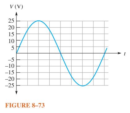
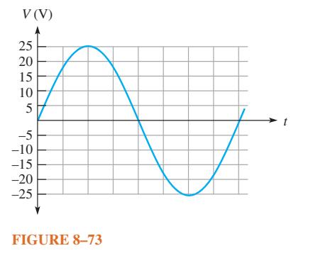
For the sine wave in Figure 8–73, determine the peak, peak-to-peak, rms, and half-cycle average values. V (V) 25 20 15 10 5 -5 -10 -15 -20 -25 FIGURE 8-73
If each horizontal division in Figure 8–73 is 1 ms, determine the instantaneous voltage value at(a) 1 ms (b) 2 ms (c) 4 ms (d) 7 ms V (V) 25 20 15 10 5 -5 -10 -15 -20 -25 FIGURE 8-73
How long does it take a 10 kHz sine wave to complete 100 cycles?
In Figure 8–73, what is the instantaneous voltage at (a) 45° (b) 90° (c) 180° V (V) ***** 25 20 15 10 5 -5 -10 -15 -20 -25 FIGURE 8-73
Sine wave A has a positive-going zero crossing at 30° from a reference. Sine wave B has a positive-going zero crossing at 45° from the same reference. Determine the phase angle between the two signals. Which signal leads?
One sine wave has a positive peak at 75° and another has a positive peak at 100°. How much is each sine wave shifted in phase from the 0° reference? What is the phase angle between them?
Convert the following angular values from radians to degrees: (a) π/8 TT/8 (b) T/3 (C) π/2 (d) 3π/5 (e) 6π/5 (f) 1.877
Draw two sine waves as follows: Sine wave A is the reference, and sine wave B lags A by 90°. Both have equal amplitudes.
Convert the following angular values from degrees to radians: (a) 30° (b) 45° (c) 78° (d) 135° (e) 200° (f) 300°
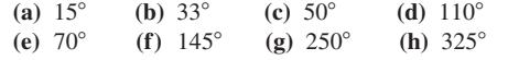
A certain sine wave has a positive-going zero crossing at 0° and an rms value of 20 V. Calculate its instantaneous value at each of the following angles: (a) 15 (e) 70 (b) 33 (f) 145 (c) 50 (g) 250 (d) 110 (h) 325
For a 0° reference sine wave with an rms value of 6.37 V, determine its instantaneous value at each of the following points: (a) 7/8 rad (e) 7 rad (b) π/4 rad (f) 3π/2 rad (c) π/2 rad (g) 27 rad (d) 37/4 rad
For a particular 0° reference sinusoidal current, the peak value is 100 mA. Determine the instantaneous value at each of the following points:(a) 35° (b) 95° (c) 190° (d) 215° (e) 275° (f) 360°
A 6 V peak sine wave is riding on a dc voltage of 8 V. If the dc voltage is lowered to 5 V, how far negative will the sine wave go?
What is the frequency of each sawtooth wave form in Figure 8–79? 0 (a) 0 10 20 30 FIGURE 8-79 40, t (us) V 0 0 (b) 100 200 t (ms)
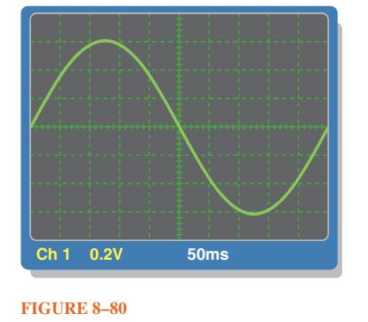
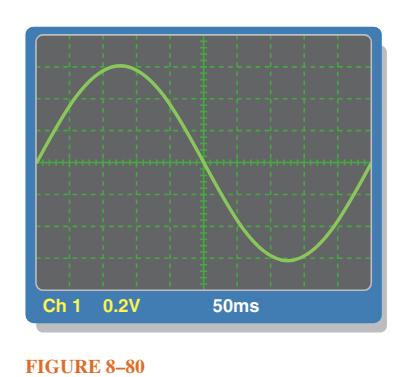
Determine the peak value and the period of the sine wave displayed on the scope screen in Figure 8–80. The horizontal axis is 0 V. Ch 1 0.2V FIGURE 8-80 50ms
Determine the rms value and the frequency of the sine wave displayed on the scope screen in Figure 8–80. Ch 1 0.2V FIGURE 8-80 50ms
What is the fundamental frequency of the square wave mentioned in Problem 38? Data in Problem 38?A square wave has a period of 40 μs. List the first six odd harmonics.
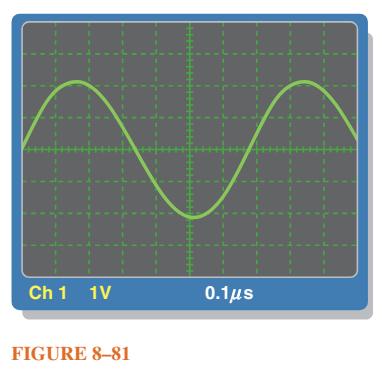
Determine the rms value and the frequency of the sine wave displayed on the scope screen in Figure 8–81. The horizontal axis is 0 V. Ch 1 1V FIGURE 8-81 0.1μs
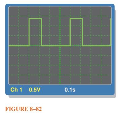
Find the amplitude, pulse width, and duty cycle for the pulse waveform displayed on the scope screen in Figure 8–82. The horizontal axis is 0 V. Ch 1 0.5V FIGURE 8-82 0.1s
Why is spectral purity important for a sinusoidal signal generator?
What is a modulating signal and how is it applied to an analog signal generator?
Assume you are testing a circuit with different frequencies to measure its response. Why is it important to check the signal level from the generator each time the frequency is changed?
A non sinusoidal waveform called a stair step is shown in Figure 8–84. Determine its average value. V (V) 10 6 54 4 3 3 2 2 1 1 2 3 4 T FIGURE 8-84 5 6 7 t (ms)
What is the difference between burst mode and gated mode for a generator?
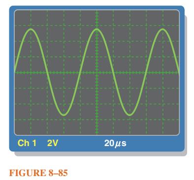
Refer to the oscilloscope screen in Figure 8–85.(a) How many cycles are displayed? (b) What is the rms value of the sine wave? (c) What is the frequency of the sine wave? M Ch 1 2V FIGURE 8-85 20s
The cross-sectional area of a magnetic field is increased, but the flux remains the same. Does the flux density increase or decrease?
In a certain magnetic field the cross-sectional area is 0.5 m2 and the flux is 1500 μWb. What is the flux density?
What is the flux in a magnetic material when the flux density is 2500 × 10-6 T and the cross-sectional area is 150 cm2?
What is the magnetomotive force in a 500 turn coil of wire with 3 A through it?
Typically, when a solenoid is activated, is the plunger extended or retracted?
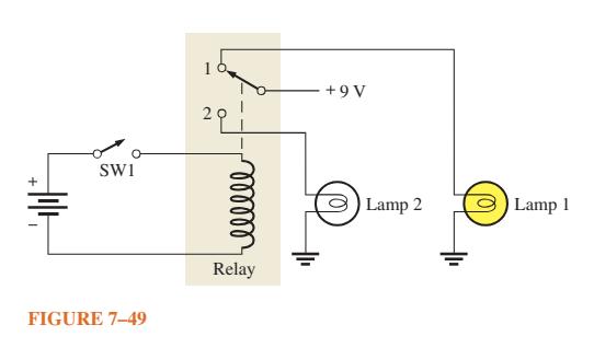
Explain the sequence of events in the circuit of Figure 7–49 starting when switch 1 (SW1) is closed. + SWI FIGURE 7-49 16 ellele Relay +9V Lamp 2 Lamp 1
(a) What force moves the plunger when a solenoid is activated? (b) What force causes the plunger to return to its at-rest position?
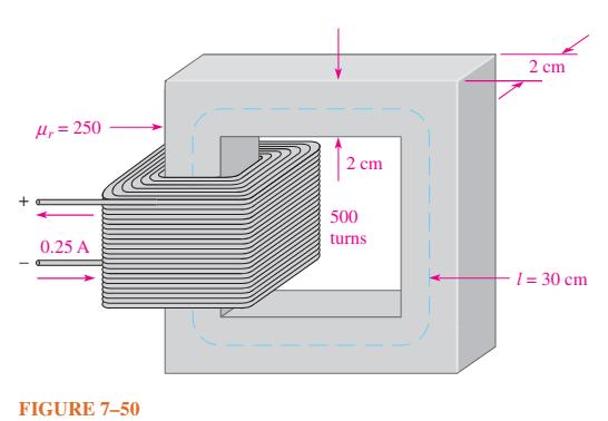
How can the flux density in Figure 7–50 be changed without altering the physical characteristics of the core?Data in Figure 7–50 + 1 H₁ = 250 0.25 A FIGURE 7-50 2 cm 500 turns 2 cm 1 = 30 cm
What causes the pointer in a d’Arsonval meter movement to deflect when there is current through the coil?
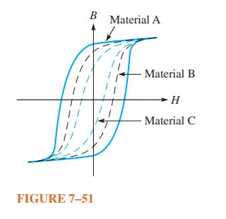
Determine from the hysteresis curves in Figure 7–51 which material has the most retentivity. B FIGURE 7-51 Material A Material B · Η Material C
What is the magnetizing force in Problem 9 if the length of the core is 0.2 m?Data in Problem 9.What is the magnetomotive force in a 500 turn coil of wire with 3 A through it?
According to Faraday’s law, what happens to the induced voltage across a given coil if the rate of change of magnetic flux doubles?
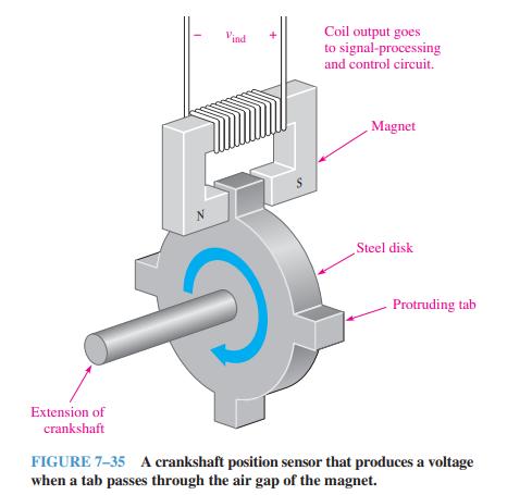
In Figure 7–35, why is there no induced voltage when the steel disk is not rotating? Vind T Extension of crankshaft S Coil output goes to signal-processing and control circuit. Magnet Steel disk Protruding tab FIGURE 7-35 A crankshaft position sensor that produces a voltage when a tab
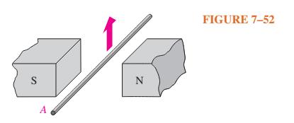
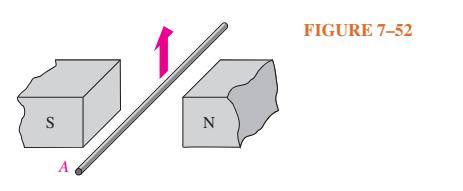
(a) For the conductor shown in Figure 7–52 ,what is the polarity of the end marked with the letter A ? (b) Assuming a complete path is provided and current is in the direction you indicated, what direction is the induced force on the conductor? S A N FIGURE 7-52
A 20 cm long conductor is moving upward between the poles of a magnet as shown in Figure 7–52. The pole faces are 8.5 cm on each side and the flux is 1.24mWb. The motion produces an induced voltage across the conductor of 44mV. What is the speed of the conductor? S A N FIGURE 7-52
The voltage induced across a certain coil is 100 mV. A 100 Ω resistor is connected to the coil terminals. What is the induced current?
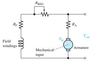
Assume the self-excited shunt dc generator in Figure 7–43 has a load connected to it that draws 12 A. If the field windings draw 1.0 A, what is the armature current?Data in Figure 7–43. RE Field windings www ell RREG Mechanical- input VG. RA V Armature O
If a generator is 80% efficient and delivers 45 W to a load, what is the input power?
(a) What power is developed by a motor that turns at 1200 rpm and has a torque of 3.0 N-m? (b) What is the horsepower rating of the motor? (746 W = 1 hp)
Assume a motor dissipates 12 W internally when it delivers 50 W to a load. What is the efficiency?
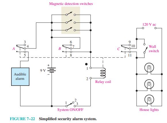
Explain the purpose of each of the three sets of relay contacts (A, B, and C) in Figure 7–22. 3 Audible alarm Magnetic detection switches 9V = B 2 tele Relay coil System ON/OFF FIGURE 7-22 Simplified security alarm system. 10 120 V ac Wall switch House lights
A basic one-loop dc generator is rotated at 60 rps. How many times each second does the dc output voltage peak (reach a maximum)?
Assume that another loop of wire, 90° from the first loop, is added to the dc generator in Problem 28. Describe the output voltage. Let the maximum voltage be 10 V.Data in Problem 28.A basic one-loop dc generator is rotated at 60 rps. How many times each second does the dc output voltage peak
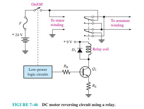
For the DC motor reversing circuit in Figure 7–46, assume the polarity to the armature is opposite to the polarity of the stator. Is the relay coil energized or not? Explain your answer. F + 24 V On/Off Low-power logic circuits To stator winding +9V o D₁ RB ww ell Relay coil Q₁ RE To
Identify the series and parallel relationships in Figure 6–74 as seen from the source terminals. Vs 3V + R 10 R5 10 FIGURE 6-74 R 33 R3 33 R4 33
Assume you have a meter that has a 100 μA full-scale deflection current and an internal resistance of 80 Ω. What shunt resistance would you specify to cause the meter to read 1 mA full scale?
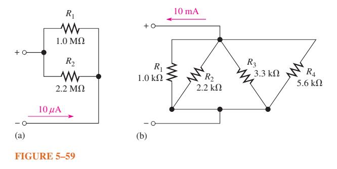
Determine the total power in each circuit of Figure 5–59. +0 (a) R₁ Μ 1.0 ΜΩ R₂ Μ 2.2 ΜΩ 10 μα FIGURE 5-59 +0 R₁ 1.0 ΚΩ (b) 10 mA R₂ 2.2 ΚΩ R3 2.3.3 ΚΩ R4 5.6 ΚΩ
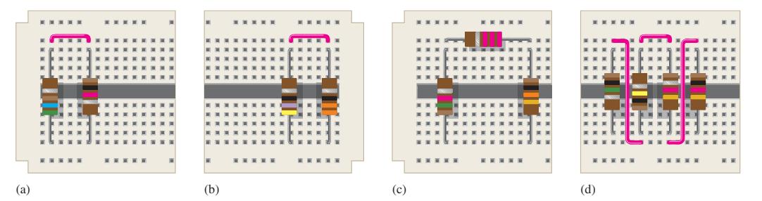
Find the total resistance of each group of series resistors shown in Figure 4–67. Data in Figure 4–67 . (a) ***** (b) (c) **** (d) *****
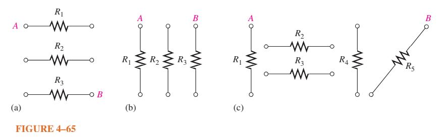
Connect each set of resistors in Figure 4–65 in series between points A and B. A o (a) R www R R3 www FIGURE 4-65 -O B R (b) R R3 B R www R4 R Ju ww R (c) R5 B
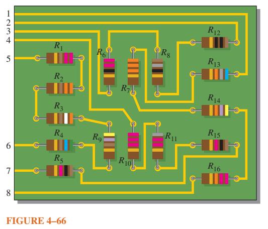
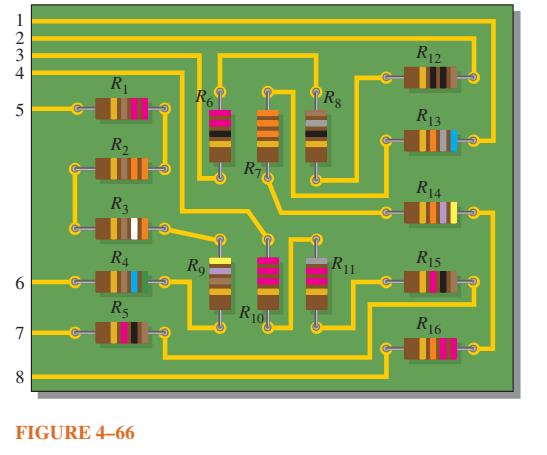
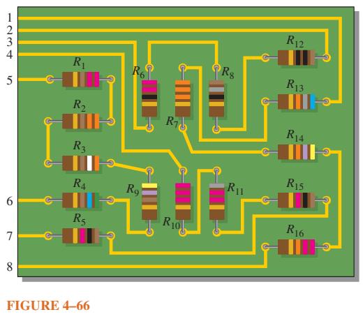
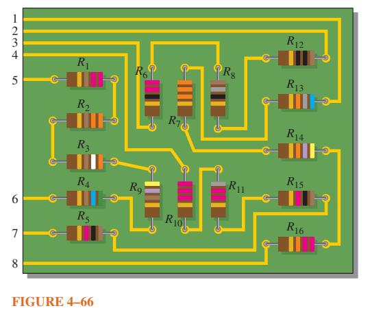
Determine which resistors in Figure 4–66 are in series. Show how to interconnect the pins to put all the resistors in series. Data in Figure 4–66 1234 5 6 7 8 R R R3 R4 R5 FIGURE 4-66 Ro Ro R R0 Rs R1 R12 R13 R14 R15 R16
Determine the resistance between pins 1 and 8 in the circuit board in Figure 4–66. 1234 5 6 7 8 R R R3 RA Rs FIGURE 4-66 Ro Ro 1 R Riol Rg R11 R12 R13 R14 R15 R16
Determine the resistance between pins 2 and 3 in the circuit board in Figure 4–66. 1234 4 5 6 7 8 R R R3 R4 R5 FIGURE 4-66 R6 R Rg E R0 Rg R11 R12 R13 R14 R15 R16
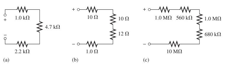
Determine RT for each circuit in Figure 4–68. Show how to measure RT with an ohmmeter. (2) Μ 1.0 ΚΩ Μ 2.2 ΚΩ 4.7 ΚΩ + - (b) Μ 10 Ω 1.0 Ω 10 Ω 12 Ω + (c) Μ ΜΜ 1.0 ΜΩ 560 ΚΩ Μ 10 ΜΩ 1.0 ΜΩ 680 ΚΩ
An 82 Ω resistor and a 56 Ω resistor are connected in series. What is the total resistance?
What is the total resistance of twelve 5.6 kΩ resistors in series?
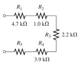
The total resistance in Figure 4–69 is 20 kΩ. What is the value of R5?Data in Figure 4–69. R₁ Μ 47 ΚΩ R₂ Μ Μ 10 ΚΩ R3 R5 ΜΜ 3.9 ΚΩ R4 2.2 ΚΩ
Six 47 Ω resistors, eight 100 Ω resistors, and two 22 Ω resistors are in series. What is the total resistance?
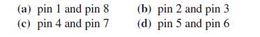
Determine the resistance between each of the following sets of pins on the PC board in Figure 4–66. 5 6 7 8 R R3 R4 R5 FIGURE 4-66 R Rg R11 THE R10 R12 R13 R14 R15 R16
If all the resistors in Figure 4–66 are connected in series, what is the total resistance? 1234 5 7 8 R R3 R R FIGURE 4-66 R6 R Rg Ro 11 R0 R11 R12 R13 R14 R15 R16
The current from the source in Figure 4–70 is 5 mA. How much current does each milliammeter in the circuit indicate?Data in Figure 4–70 1 Vs. mA + + mA FIGURE 4-70 www R₁ + www R3 + mA www R₂
Showing 300 - 400
of 641
1
2
3
4
5
6
7
Step by Step Answers