New Semester
Started
Get
50% OFF
Study Help!
--h --m --s
Claim Now
Question Answers
Textbooks
Find textbooks, questions and answers
Oops, something went wrong!
Change your search query and then try again
S
Books
FREE
Study Help
Expert Questions
Accounting
General Management
Mathematics
Finance
Organizational Behaviour
Law
Physics
Operating System
Management Leadership
Sociology
Programming
Marketing
Database
Computer Network
Economics
Textbooks Solutions
Accounting
Managerial Accounting
Management Leadership
Cost Accounting
Statistics
Business Law
Corporate Finance
Finance
Economics
Auditing
Tutors
Online Tutors
Find a Tutor
Hire a Tutor
Become a Tutor
AI Tutor
AI Study Planner
NEW
Sell Books
Search
Search
Sign In
Register
study help
engineering
fundamentals of structural analysis
Fundamentals Of Structural Analysis 5th Edition Kenneth Leet, Chia-Ming Uang, Joel Lanning - Solutions
The cross sections of the columns and girder of the frame in Figure P13.9 are identical. Carry out an approximate analysis of the frame by estimating the location of the points of inflection in the girder. The analysis is to include evaluating the support reactions and drawing the moment curves for
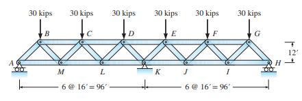
Carry out an approximate analysis of the truss in Figure \(\mathrm{P} 13.10\) by treating it as a continuous beam of constant cross section. As part of the analysis, evaluate the forces in members \(D E\) and \(E F\) and compute the reactions at \(A\) and \(K\). 30 kips B M 30 kips L 6 @ 16' = 96'
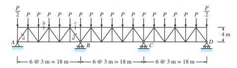
Use an approximate analysis of the continuous truss in Figure P13.11 to determine the reactions at \(A\) and \(B\). Also evaluate the forces in bars \(a,b, c\), and \(d\). Given: \(P=9 \mathrm{kN}\). I PPPI - 6@3m = 18 m 18 m 6@3m=18m - 6@3m=18m- | 4m D +
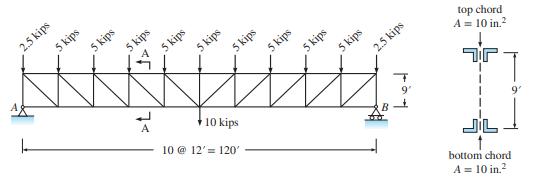
Estimate the deflection at midspan of the truss in Figure P13.12, treating it as a beam of constant cross section. The area of both the top and bottom chords is \(10 \mathrm{in} .{ }^{2} . E=29,000 \mathrm{kips} / \mathrm{in} .{ }^{2}\). The distance between the centroids of the top and bottom
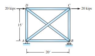
Determine the approximate values of force in each member of the truss in Figure P13.13.Assume that the diagonals can carry either tension or compression force. 20 kips 15' A 20' C B 20 kips
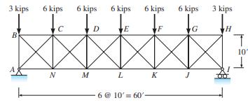
Determine the approximate values of bar force in the members of the truss in Figure P13.14 for the following two cases:(a) Diagonal bars are slender and can carry only tension.(b) Diagonal bars do not buckle and may carry either tension or compression. 3 kips B 6 kips N 6 kips M D 6 kips L E 6 kips
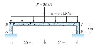
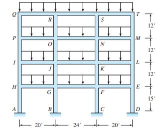
(a) All beams of the frame in Figure P13.15 have the same cross section and carry a uniformly distributed gravity load of \(3.6 \mathrm{kips} / \mathrm{ft}\). Estimate the approximate value of axial load and the moment at the top of columns \(A H\) and \(B G\). Also estimate the shear and moment at
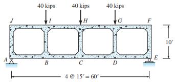
Using an approximate analysis of the Vierendeel truss in Figure P13.16, determine the moments and axial forces acting on free bodies of members \(A B, B C, I B\), and \(H C\). 40 kips B 40 kips H C 4 @ 15' 60' 40 kips D G E T 10'
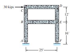
Determine the moments and axial forces in members of the frame in Figure 13.17, using the portal method. Compare the results with those produced by the cantilever method. 30 kips C B H 25'- D E F 12' 16'
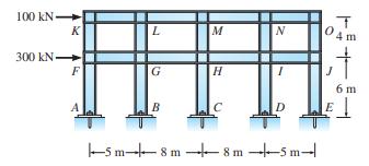
Computer Study—comparison of cantilever and portal methods with an exact analysis. (a) Determine the moments, shear, and axial forces in the members of the frame in Figure P13.18, using the portal method. (b) Repeat the analysis using the cantilever method. Assume the area of the interior columns
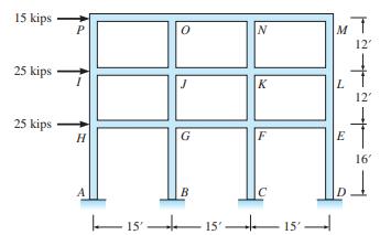
Computer Study—comparison of cantilever and portalmethods with an exactanalysis. (a) Analyze the two-story frame in Figure P13.19 by the portal method. (b) Repeat the analysis using the cantilever method. Assume the area of the interior columns is twice the area of the exterior columns. Assume
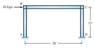
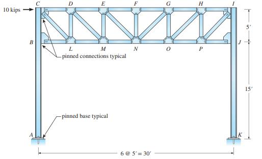
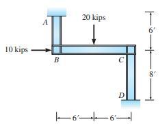
Computer Study-comparison of approximate analysis with an exact analysis. (a) Use approximate analysis to compute the reactions and draw the moment diagrams for column \(A B\) and girder \(B C\) of the frame in Figure P13.20, and draw the deflected shape. Consider column bases are fixed. (b) Repeat
Computer Study—comparison of approximate analysis with exact analysis. Consider the structures in Figures P13.21, respectively. (a) Use approximate analysis to compute the reactions and draw moment diagram for the column AB and draw the approximate deflected shape of the frame. (b) Determine
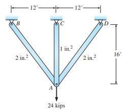
The structure in Figure P14.1 is composed of three pin-connected bars. The bar areas are shown in the figure. Given: \(E=30,000 \mathrm{kips} / \mathrm{in}^{2}\).(a) Compute the stiffness coefficient \(K\) associated with a 1-in. vertical displacement of joint \(A\). (b) Determine the vertical
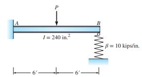
The cantilever beam in Figure P14.2 is supported on a spring at joint \(B\). The spring stiffness is 10 kips/in. Given: \(E=30,000\) kips/in. \({ }^{2}\)(a) Compute the stiffness coefficient associated with a 1-in. vertical displacement at joint \(B\). (b) Compute the vertical deflection of the
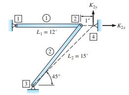
The pin-connected bar system in Figure P14.3 is stretched \(1 \mathrm{in.}\) horizontally and connected to the pin support 4. Determine the horizontal and vertical components of force that the support must apply to the bars. Area of bar \(1=2 \mathrm{in} .^{2}\), area of bar \(2=3 \mathrm{in}
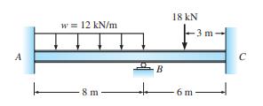
Analyze the beam in Figure P14.4.After member end moments are determined, compute all reactions and draw the moment diagrams. \(E I\) is constant. A w = 12 kN/m 8 m- B 18 kN -3 m- 6 m C
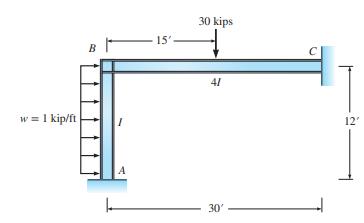
Analyze the steel rigid frame in Figure P14.5.After member end moments are evaluated, compute all reactions and the moment diagram for beam \(B C\). w = 1 kip/ft I A 15' 30 kips 41 30' C 12'
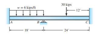
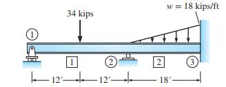
Analyze the beam in Figure P14.6.Compute all reactions and draw the shear and moment diagrams. Given: \(E I\) is constant. w = 6 kips/ft 18' B 30 kips 24'- 12'-
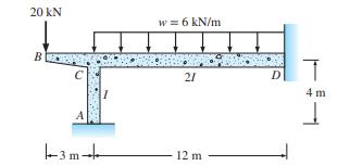
Analyze the reinforced concrete frame in Figure P14.7.Determine all reactions. \(E\) is constant. 20 kN C -3 m w = 6 kN/m 21 12 m D T 4 m -1
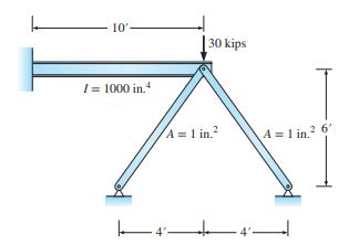
The structure in Figure P14.8 is composed of a beam supported by two struts at the cantilever end. Compute all reactions and the strut member forces. Use \(E=30,000\) kips/in. \({ }^{2}\). 10'- I= 1000 in.4 30 kips A = 1 in. 4 A=1 in.2 6'
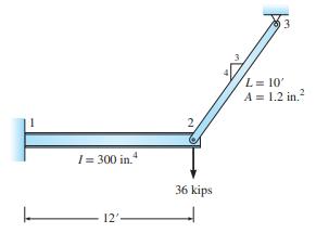
The cantilever beam in Figure P14.9 is connected to a bar at joint 2 by a pin. Compute all reactions. Given: \(E=30,000 \mathrm{kips} / \mathrm{in}\). \(^{2}\). Ignore axial deformation of the beam. 1 = 300 in. 12' 2 36 kips 53 L= 10' A = 1.2 in.
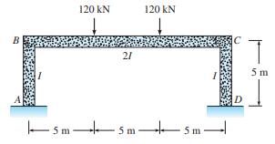
Analyze the rigid frames in Figure P14.10, using symmetry to simplify, P14.10 the analysis. Compute all reactions and draw the moment diagrams for all members. Also \(E\) is constant. B 1 120 KN 21 120 KN I | 5 m 5 m 5m- D 5 m
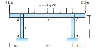
Analyze the rigid frames in Figure P14.11, using symmetry to simplify, P14.11 the analysis. Compute all reactions and draw the moment diagrams for all members. Also \(E\) is constant. 8 kips B -10 I w = 2 kips/ft 41 40' C D 8 kips 10- 18'
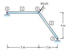
Using the stiffness method, write and solve the equations of equilibrium required to determine the horizontal and vertical components of deflection at joint 1 in Figure P15.1.For all bars \(E=200 \mathrm{GPa}\) and \(A=800 \mathrm{~mm}^{2}\). 5m 80 KN , 2 - 3 m 4m
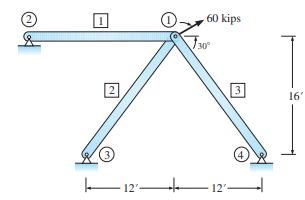
Using the stiffness method, determine the horizontal and vertical components of displacement of joint 1 in Figure P15.2.Also compute all bar forces. For all bars, \(L\) \(=20 \mathrm{ft}, E=30,000 \mathrm{kips} / \mathrm{in} .^{2}\), and \(A=3{\mathrm{in} .{ }^{2} \text {. }}^{2}\) (2) 2 12- 1. 60
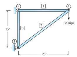
Form the structure stiffness matrix for the truss in Figure P15.3.Partition the matrix as indicated by Equation 15.30. Compute all joint displacements and reactions using Equations 15.34 and 15.35. For all bars, \(A=2\) in. \(^{2}\) and \(E=30,000\) kips/in. . . 15' (3) 3 20' 1 36 kips
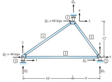
Form the structure stiffness matrix for the truss in Figure P15.4.Use the partitioned matrix to compute the displacement of all joints and reactions. Also compute the bar forces. Area of bars 1 and \(2=2.4\) in. \(^{2}\), area of bar \(3=2\) in. \({ }^{2}\), and \(E=30,000\) kips/in. \({ }^{2}\). Q
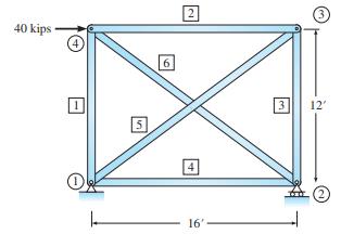
Determine all joint displacements, reactions, and bar forces for the truss in Figure P15.5.AE is constant for all bars. \(A=2\) in. \({ }^{2}, E=30,000\) kips/in. \({ }^{2}\). 40 kips S 6 2 4 16' 3 (3) 12' (2)
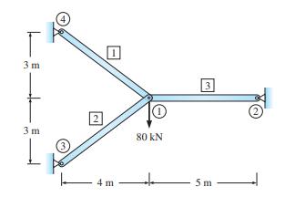
Determine all joint displacements, reactions, and bar forces for the truss in Figure P15.6.For all bars, \(A=1500 \mathrm{~mm}^{2}\) and \(E=200 \mathrm{GPa}\). 3 m 3 m L 4m 0 80 KN 3 5m
Using the stiffness method, analyze the two-span continuous beam shown in Figure P16.1 and draw the shear and moment curves EI is constant. IA 20 w = 2 kips/ft B 30'
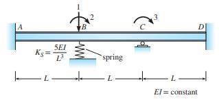
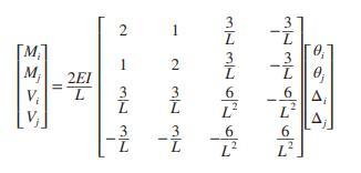
Write the stiffness matrix corresponding to the degrees of freedom 1,2, and 3 of the continuous beam shown in Figure P16.2. A SEI Ks= 12- 1 B 2 spring 3 -I+2 L D El= constant
In Problem P16.2, find the force in the spring located at B if beam ABCD supports a downward uniform load w along its entire length.Problem P16.2Write the stiffness matrix corresponding to the degrees of freedom 1,2, and 3 of the continuous beam shown in Figure P16.2. A SEI Ks= 12- 1 B 2 spring 3
Using the stiffness method, analyze the frame in Figure P16.4 and draw the shear and moment curves for the members. Neglect axial deformations. EI is constant. 10 kips B 20 kips 66 D T 6' 8'
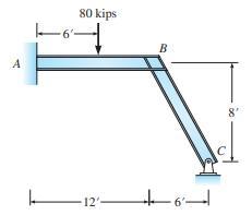
Analyze the frame in Figure P16.5 and draw the shear and moment curves for the members. Neglect axial deformation. EI is constant. A 80 kips -6- 12'- B -6'- 8'
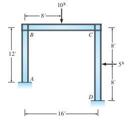
Using the stiffness method, analyze the frame in Figure P16.6 and draw the shear and moment curves for the members. Neglect axial deformations. EI is constant. 12' B A 10k 10000 16' C T 8' 8' Sk
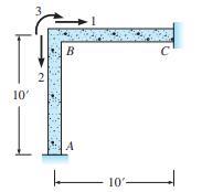
For the frame shown in Figure P16.7, write the stiffness matrix in terms of the three degrees of freedom indicated. Use both the method of introducing unit displacements and the member stiffness matrix of Equation 16.36. Given: E = 30,000 kips/in.2 ; I = 500 in.4 , and A = 15 in.2 .Eq 16.36. 10' 2
Solve Problem P16.7 using the direct summation of global element stiffness matrices.Problem P16.7For the frame shown in Figure P16.7, write the stiffness matrix in terms of the three degrees of freedom indicated. Use both the method of introducing unit displacements and the member stiffness matrix
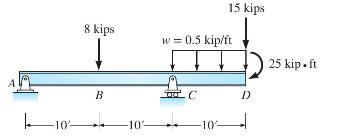
Write the equations for shear and moment between points \(B\) and \(C\) as a function of distance \(x\) along the longitudinal axis of the beam in Figure P5.1 for (a) origin of \(x\) at point \(A\) and (b) origin of \(x\) at \(D\). -10% 8 kips B 10 w = 0.5 kip/ft .C 15 kips -10 D 25 kip.ft
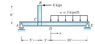
Write the equations for shear and moment between points \(D\) and \(E\). Select the origin at \(D\). 6' B D | 5 3 8 kips w = 3 kips/ft x 10'- E
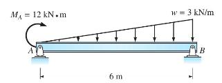
Write the equations for shear and moment between points \(A\) and \(B\). Select the origin at \(A\). Plot the graph of each force under a sketch of the beam. The rocker at \(A\) is equivalent to a roller. M = 12 kN.m 6 m w = 3 kN/m B
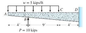
Write the equations for shear \(V\) and moment \(M\) between points \(B\) and \(C\). Take the origin at point \(A\). Evaluate \(V\) and \(M\) at point \(C\) using the equations. A 4' w = 5 kips/ft BA P = 10 kips 9'
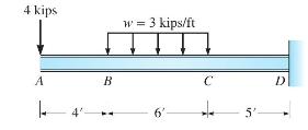
Write the equations for moment between points \(B\) and \(C\) as a function of distance \(x\) along the longitudinal axis of the beam in Figure P5.5 for ( \(a\) ) origin of \(x\) at \(A\) and (b) origin of \(x\) at \(B\). 4 kips A 4' B w = 3 kips/ft 6' C 5'
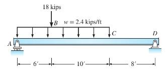
Write the equations required to express the moment along the entire length of beam in Figure P5.6. Use an origin at point \(A\), and then repeat computations using an origin at point \(D\). Verify that both procedures give the same value of moment at point \(C\). 18 kips B w = 2.4 kips/ft kot 10'-
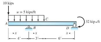
Write the equations for shear and moment using the origins shown in the figure. Evaluate the shear and moment at \(C\), using the equations based on the origin at point \(D\). 10 kips w = 5 kips/ft -X B C X -3'- D X- 32 kip.ft
Write the equations for shear \(V\) and moment \(M\) in terms of distance \(x\) along the length of the beam in Figure P5.8. Take the origin at point \(A\). 8 kips w = 4 kips/ft 10'- 15 kips B + 6'.
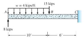
Write the equation for moment between points \(B\) and \(C\) for the rigid frame in Figure P5.9. 6 kips B 48 kips w = 6 kips/ft 16- C DA 48 kips 10' 6 kips
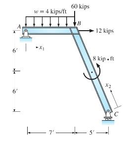
Write the equations for moment as a function of distance along the longitudinal axes for members \(A B\) and \(B C\) of the frame in Figure P5.10. Origins for each member are shown. 6' + 6' I w = 4 kips/ft XI 17'- 60 kips -7. B 12 kips 8 kip.ft 4
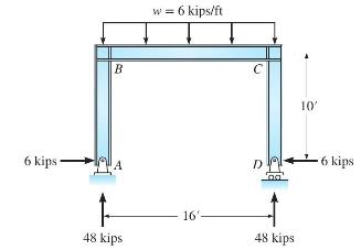
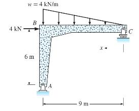
Write the equations for shear and moment between points \(B\) and \(C\) for the rigid frame in Figure P5.11. Select the origin at point \(C\). 4 kN w = 4 kN/m B 6 m L 9 m-
Consider the beam shown in Figure P5.12.(a) Write the equations for shear and moment using an origin at end A. (b) Using the equations, evaluate the moment at section 1. (c) Locate the point of zero shear between B and C. (d) Evaluate the maximum moment between points B and C. (e) Write the
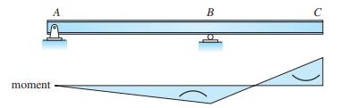
Given the moment curve for each beam, (a) sketch the deflected shape and (b) determine the applied loading qualitatively. A moment B C
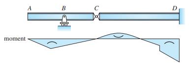
Given the moment curve for each beam, (a) sketch the deflected shape and (b) determine the applied loading qualitatively. moment A B D
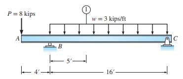
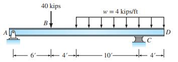
For each beam, draw the shear and moment curves label the maximum values of shear and moment, locate points of inflection, and sketch the deflected shape. 40 kips B 64 w = 4 kips/ft 10' EC D
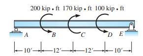
For each beam, draw the shear and moment curves label the maximum values of shear and moment, locate points of inflection, and sketch the deflected shape. A 200 kip. ft 170 kip. ft 100 kip. ft B DE 10121210
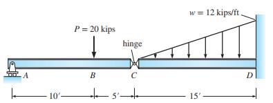
For each beam, draw the shear and moment curves label the maximum values of shear and moment, locate points of inflection, and sketch the deflected shape. A 10'- P = 20 kips B hinge +5 w = 12 kips/ft TTTTT 15'. D
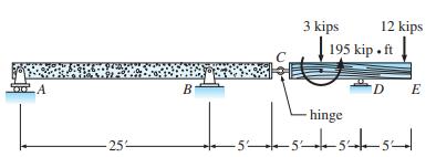
For each beam, draw the shear and moment curves label the maximum values of shear and moment, locate points of inflection, and sketch the deflected shape. A -25- B 3 kips 12 kips 195 kip. ft D E -hinge 5555 -5-
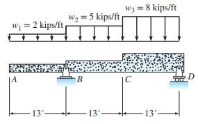
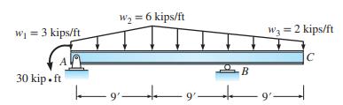
For each beam, draw the shear and moment curves label the maximum values of shear and moment, locate points of inflection, and sketch the deflected shape. w = 2 kips/ft B |A 13'- W = 5 kips/ft B 13'- W3 = 8 kips/ft 13'-
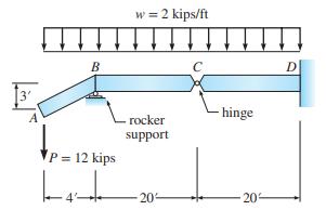
For each beam, draw the shear and moment curves label the maximum values of shear and moment, locate points of inflection, and sketch the deflected shape. 3 A B P = 12 kips Lat 4- = 2 kips/ft rocker support 20 C hinge 20 D
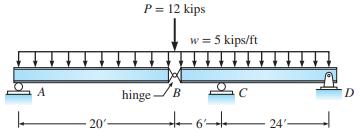
For each beam, draw the shear and moment curves label the maximum values of shear and moment, locate points of inflection, and sketch the deflected shape. 20'- P = 12 kips hinge. B w = 5 kips/ft C +6+ 24'- D
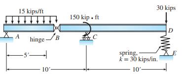
Draw the shear and moment curves for the beam in Figure P5.22, and sketch the deflected shape. Find the vertical displacement of joint \(D\). 15 kips/ft 5 hinge/B 10'- 150 kip. ft 30 kips spring, k = 30 kips/in. 10'-
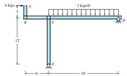
Draw the shear and moment curves for each member of the frame in Figure P5.23. Sketch the deflected shape. 6 kips 3' 12' B A 6' C E 3 kips/ft 18'
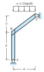
Draw the shear and moment curves for each member of the frame in Figure P5.24. Sketch the deflected shape. 6 m 10 kN B 3 m-3m-4- -6m- w = 2 kN/m D -6m- E
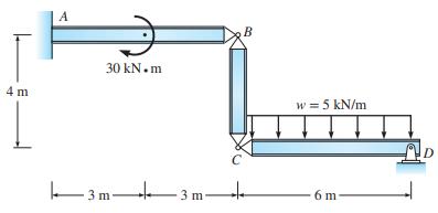
Draw the shear and moment curves for each member of the frame in Figure P5.25. Sketch the deflected shape hinges at \(B\) and \(C\). 4 m A 30 kN.m 3m- 3 m B w = 5 kN/m 6 m D
Draw the shear and moment curves for the beam in Figure P5.26. Sketch the deflected shape. W = 3 kips/ft 30 kip.ft W = 6 kips/ft 9'- -B 9' W3 = 2 kips/ft C
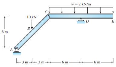
Draw the shear and moment curves for each member of the frame in Figure P5.27. Sketch the deflected shape. 4 kips B 10 kips 8'- w = 2 kips/ft C A 8'. D 15'
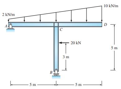
Draw the shear and moment curves for each member of the frame in Figure P5.28. Sketch the deflected shape. 2 kN/m -5m- B C 3 m 20 kN 5 m 10 kN/m D 5m
Draw the shear and moment curves for each member of the frame in Figure P5.29. Sketch the deflected shape. T 3' 5' B w = 2 kips/ft 4
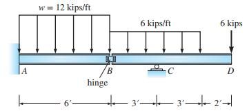
Draw the shear and moment curves for each member of the beam in Figure P5.30. Sketch the deflected shape. The shear connection at \(B\) acts as a hinge. |A w = 12 kips/ft 6'- B hinge 6 kips/ft C 6 kips D 3 3 2-d 3'- 3'-
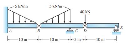
Draw the shear and moment curves for each member of the beam in Figure P5.31. Sketch the deflected shape. A -5 kN/m 10 m B 5 kN/m -10 m 40 KN C D 4-5m- 10 m E
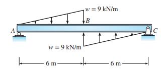
Draw the shear and moment curves for the beam in Figure P5.32. Sketch the deflected shape. w = 9 kN/m 6 m- w = 9 kN/m B + -6 m- C
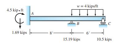
Draw the shear and moment curves for the indeterminate beam in Figure P5.33. Reactions at support \(A\) are given. Sketch the deflected shape. 4.5 kip.ft 1.69 kips A 8'- w = 4 kips/ft -B - 15.19 kips 6' C 10.5 kips
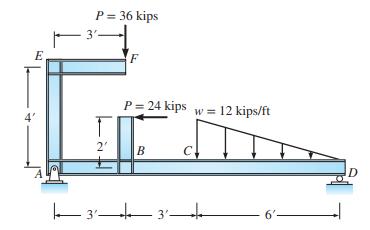
Draw the shear and moment curves for the beam in Figure P5.34. Sketch the deflected shape. E 4' P = 36 kips 3' T 2' F P= 24 kips w = 12 kips/ft B C | 3' 3 3'- 6'-
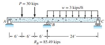
Draw the shear and moment curves for the beam in Figure P5.35. Reaction at support \(B\) is given. Locate all points of zero shear and moment. Sketch the deflected shape. P = 30 kips 16+6+6- B RB = 85.49 kips w = 3 kips/ft 24' C
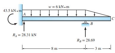
Draw the shear and moment curves for each indeterminate beam. Reactions are given. Label maximum values of shear and moment. Locate all inflection points, and sketch the deflected shape. 43.5 kN.m C A R = 28.31 KN L w = 6 kN.m 8 m - B RB = 28.69 -3 m C
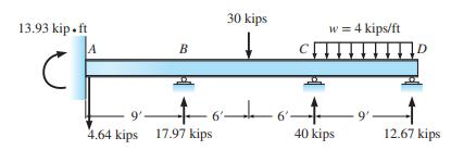
Draw the shear and moment curves for each indeterminate beam. Reactions are given. Label maximum values of shear and moment. Locate all inflection points, and sketch the deflected shape. 13.93 kip.ft A B 30 kips 4.64 kips 17.97 kips 94661 w = 4 kips/ft CH 40 kips 9' D 12.67 kips
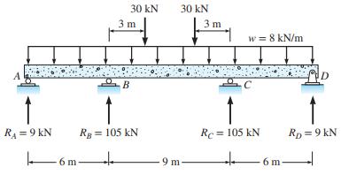
Draw the shear and moment curves and sketch the deflected shape. R = 9 KN 30 kN 6m 3 m B RB = 105 KN 30 kN 9 m 3m w = 8 kN/m RC = 105 KN 6 m RD = 9 kN
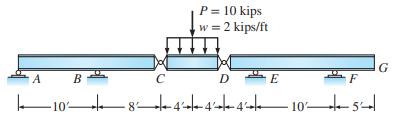
Draw the shear and moment curves and sketch the deflected shape. A 10% B C P = 10 kips w = 2 kips/ft D E F -8-4--4--4-105 G
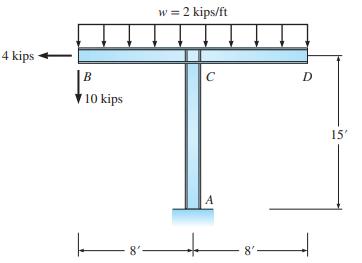
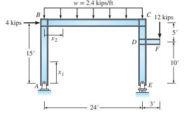
(a) Draw the shear and moment curves for the frame in Figure P5.40. Sketch the deflected shape. (b) Write the equations for shear and moment in column AB. Take the origin at A. (c) Write the shear and moment equations for girder BC. Take the origin at joint B. 4 kips 15' B X2 w = 2.4 kips/ft 24' D
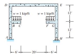
Draw the shear and moment curves for each member of the rigid frame in Figure P5.41. Sketch the deflected shape. D w = 1 kip/ft B C Lo 6'- 20 w = 1 kip/ft F G tot E 12' 12' 4
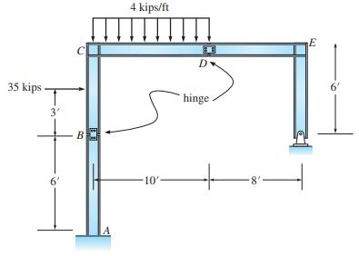
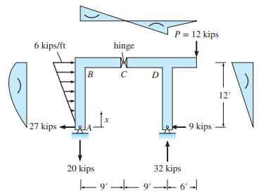
Draw the shear and moment curves for each member of the frame in Figure P5.42. Sketch the deflected shape. Joints B and D are rigid. 35 kips. 3' 6' B 4 kips/ft -10' 31 D hinge. 8 T E 6'
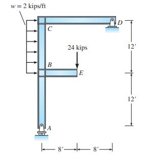
Draw the moment curves for each member of the frame in Figure P5.43. Sketch the deflected shape of the frame. Joints \(B\) and \(C\) are rigid. w = 2 kips/ft C B 24 kips 8'- E | 88 D 12' 12'
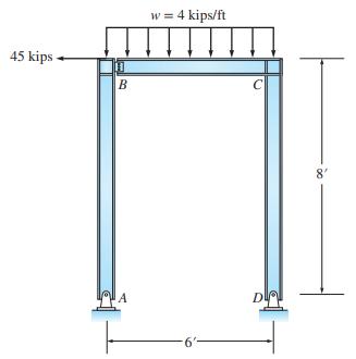
Draw the shear and moment curves for each member of the frame in Figure P5.44. Sketch the deflected shape. Treat the shear plate connection at \(B\) as a hinge. 45 kips B A w = 4 kips/ft 6" C DIA 8'
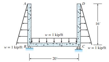
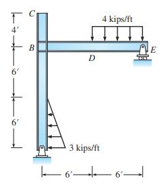
Draw the shear and moment curves for each member of the frame and draw the deflected shape. Joints \(B\) and \(C\) are rigid. w = 1 kip/ft B w = 1 kip/ft 20- D 16' w = 1 kip/ft
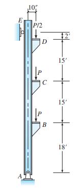
Draw the shear and moment curves for the column in Figure P5.46. Sketch the deflected shape. The load \(P\) is equal to \(55 \mathrm{kips}\), and the load is eccentric from the column centerline with an eccentricity of 10 in. E A ,10, P12 D P C B $2 15' ++ 15' 18'
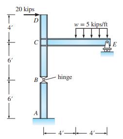
For the frame in Figure P5.47, draw the shear and moment curves for all members. Next sketch the deflected shape of the frame. Show all forces acting on a free-body diagram of joint \(C\). T 6' 20 kips 6 D C B A hinge 4' w = 5 kips/ft E
(a) Sketch the deflected shape of the frame in Figure P5.48. Reactions and moment curves are given. Curvature is also indicated. Joints \(B\) and \(D\) are rigid. The hinge is located at point \(C\). (b) Using an origin at \(A\), write the equations for shear and moment in member \(A B\) in terms
Draw the shear and moment curves for all members of the frame in Figure P5.49. Sketch the deflected shape. T 4' 6' 6' L B D 3 kips/ft 6'- 4 kips/ft +6 6' E
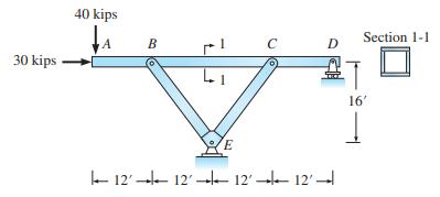
The hollow structural section beam \(A B C D\) in Figure P5.50 is supported by a roller at point \(D\) and two links \(B E\) and \(C E\). Compute all reaction, draw the shear and moment curves for the beam, and sketch the deflected shape of the structure. 30 kips 40 kips B 1 1 E C 12121212 D
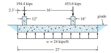
The combined footing shown in Figure P5.51 is designed as a narrow reinforced concrete beam. The footing has been proportioned so that the resultant of the column loads passes through the centroid of the footing, producing a uniformly distributed soil pressure on the base of the footing. Draw the
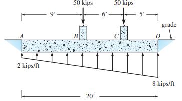
The two concentrated loads, supported on the combined footing in Figure P5.52, produce a trapezoidal distribution of soil pressure. Construct the shear and moment curves. Label all ordinates of the curves. Sketch the deflected shape. A 2 kips/ft 9'- 50 kips B 20' 6' 50 kips C 5 grade D 1 8 kips/ft
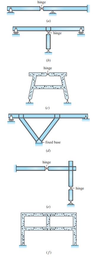
Classify the structures in Figure P5.53. Indicate whether stable or unstable. If stable, indicate whether determinate or indeterminate. If indeterminate, give the degree. 2 W hinge (a) (b) hinge (c) fixed base (d) hinge hinge (f) hinge
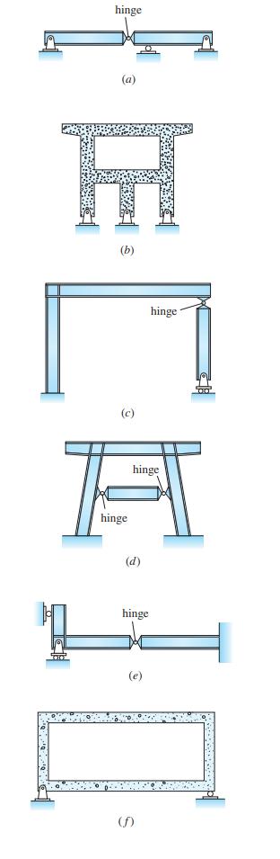
Classify the structures in Figure P5.54. Indicate whether stable or unstable. If stable, indicate whether determinate or indeterminate. If indeterminate, give the degree. hinge (a) H (c) hinge A hinge (d) hinge (e) hinge (f)
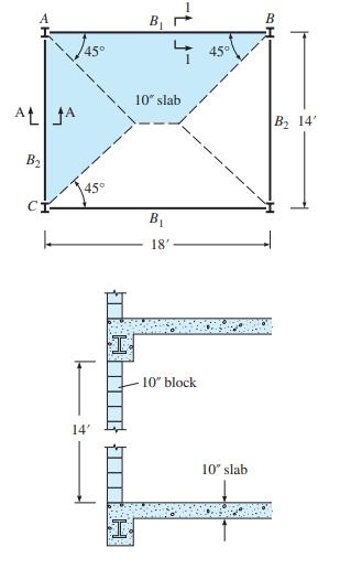
The corner panel of a typical floor of a warehouse is shown in Figure P5.55. It consists of a 10-in.thick reinforced concrete slab supported on steel beams. The slab weighs 125 lb/ft2. The weight of light fixtures and utilities suspended from the bottom of the slab is estimated to be 5 lb/ft2. The
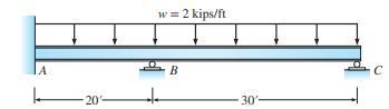
Computer analysis of a continuous beam. The continuous beam in Figure P5.56 is constructed from a W12 × 152 wide flange steel section with A = 44.7 in.2 and I = 1430 in.4. Determine the reactions, plot the shear and moment curves and the deflected shape. Evaluate the deflections. Neglect weight of
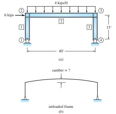
Computer analysis. The columns and girder of the indeterminate rigid frame in Figure P5.57a are fabricated from a W18 × 130 wide flange steel section: A = 38.2 in.2 and I = 2460 in.4. The frame is to be designed for a uniform load of 4 kips/ft and a lateral wind load of 6 kips; use E = 29,000
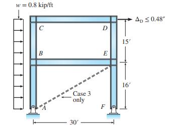
Computer investigation of wind load on a building frame.Case 1: The columns and girders of the rigid building frame in Figure P5.58 have been designed initially for vertical load as specified by the building code. Floor beams are connected to columns by rigid joints. As part of the design, the
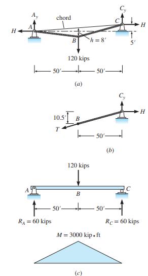
Determine the reactions at the supports produced by the 120-kip load at midspan (Figure 6.6) (a) using the equations of static equilibrium(b) using the general cable theorem. Neglect the weight of the cable.Figure 6.6 H R = 60 kips chord 50' + B 120 kips (a) 10.5' B T 50'- 120 kips B h=8' (c)
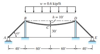
A cable-supported roof carries a uniform load w = 0.6 kip/ft (Figure 6.7a). If the cable sag at midspan is set at 10 ft, what is the maximum tension in the cable (a) between points B and D (b) between points A and B?Figure 6.7a 45 40 B w = 0.6 kip/ft C h = 10' 30' 60'- + 60'- D 40 E
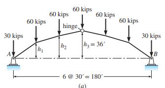
Establish the shape of the funicular arch for the set of loads acting on the trussed arch in Figure 6.14a. The rise of the arch at midspan is set at 36 ft.Figure 6.14a 30 kips ' 60 kips hi 60 kips 60 kips hinge h 60 kips h=36' 6 @ 30' 180'- (a) 60 kips 30 kips NB
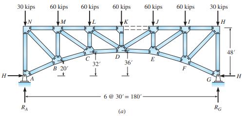
The three-hinged arch truss shown in Figure 6.15a has a bottom chord of the same funicular shape as that found in Example 6.3. To demonstrate one benefit of using a funicular arch shape, (a) analyze the truss assuming the applied loads represent the dead load of the structure,(b) analyze the truss
Showing 100 - 200
of 570
1
2
3
4
5
6
Step by Step Answers