New Semester
Started
Get
50% OFF
Study Help!
--h --m --s
Claim Now
Question Answers
Textbooks
Find textbooks, questions and answers
Oops, something went wrong!
Change your search query and then try again
S
Books
FREE
Study Help
Expert Questions
Accounting
General Management
Mathematics
Finance
Organizational Behaviour
Law
Physics
Operating System
Management Leadership
Sociology
Programming
Marketing
Database
Computer Network
Economics
Textbooks Solutions
Accounting
Managerial Accounting
Management Leadership
Cost Accounting
Statistics
Business Law
Corporate Finance
Finance
Economics
Auditing
Tutors
Online Tutors
Find a Tutor
Hire a Tutor
Become a Tutor
AI Tutor
AI Study Planner
NEW
Sell Books
Search
Search
Sign In
Register
study help
engineering
fundamentals of structural analysis
Fundamentals Of Structural Analysis 5th Edition Kenneth Leet, Chia-Ming Uang, Joel Lanning - Solutions
When a moment frame does not exceed 12 stories in height and the story height is at least \(10 \mathrm{ft}\), the ASCE standard provides a simpler expression to compute the approximate fundamental period:T=0.1 Nwhere \(N=\) number of stories. Recompute \(T\) with the above expression and compare it
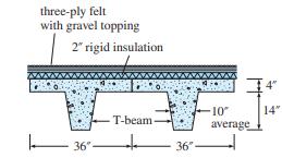
A three-ply asphalt felt and gravel roof over 2-in.-thick insulation board is supported by 18-in-deep precast reinforced concrete beams with 3-ftwide flanges (Figure 2.2). If the insulation weighs 3 lb/ft2 and the asphalt roofing weighs 5__1/2 lb/ft2, determine the total dead load, per foot of
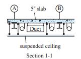
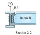
The steel framing plan of a small building is shown in Figure 2.3a. The floor consists of a 5-in.-thick reinforced concrete slab supported on steel beams (see section 1-1 in Figure 2.3b). Beams are connected to each other and to the corner columns by clip angles; see Figure 2.3c. The clip angles
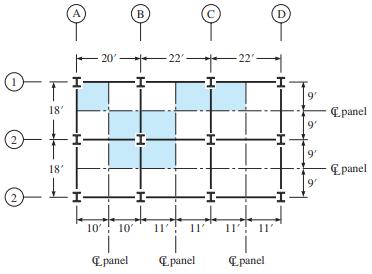
Using the tributary area method, compute the floor dead loads supported by columns A1 and B2 in Figure 2.4. The floor system consists of a 6-in.-thick reinforced concrete slab weighing 75 lb/ft2. Allow 15 lb/ft2 for the weight of floor beams, utilities, and a ceiling suspended from the floor. The
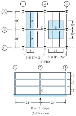
For the three-story building shown in Figure 2.5a and b, calculate the design live load supported by (1) Floor beam A, (2) Girder B,(3) The interior column C located at grid 2-B in the first story. Assume a 50 lb/ft2 design live load, Lo, on all floors including the roof.Figure 2.5a/b A B 20' +
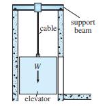
Determine the magnitude of the concentrated force for which the beam in Figure 2.6 supporting an elevator must be designed. The elevator, which weighs 3000 lb, can carry a maximum of six people with an average weight of 160 lb.Figure 2.6 cable W elevator support beam
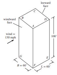
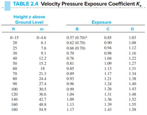
Determine the wind pressure distribution on the four sides of an eightstory hotel located on relatively flat ground approximately 2500 ft above sea level; the Risk Category II basic wind speed is 100 mph. Consider the case of a strong wind acting directly on face AB of the building in Figure 2.17a.
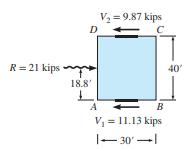
The mapped wind velocity acting on the 45-ft-high, three-story building in Figure 2.19a is 90 mph. If exposure condition C applies, determine the wind force transmitted to the building’s foundations by each of the two large reinforced concrete shear walls that make up the main wind-resisting
Determine the design seismic forces acting at each floor of the six-story office building in Figure 2.22. The structure of the building consists of steel moment frames (all joints are rigid) that have an R value of 8. The 75-ft-tall building is located in a high seismic region with SD1 = 0.4g and
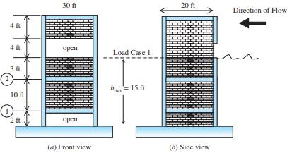
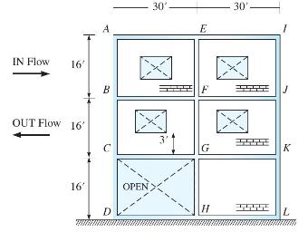
Determine the horizontal and vertical loads for tsunami Load Case 1 on the two-story building shown in Figure 2.28. It is located in an area prone to tsunami flooding, so it has been built with an open area to allow water to pass under the building. However, the first story is completely enclosed,
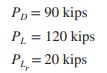
A column in a building is subject to gravity load only. Using the tributary area concept, the axial loads produced by the dead load, live load, and roof live load are What is the required axial strength of the column? PD = 90 kips L P = 120 kips P = 20 kips
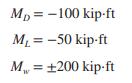
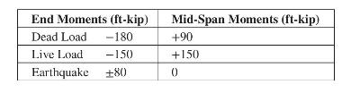
To determine the required flexural strength at one end of a beam in a concrete frame, the moments produced by dead, live, and wind load arewhere the minus sign indicates that the beam end is subject to counter clockwise moment while the plus sign indicates clockwise moment. Both the plus and minus
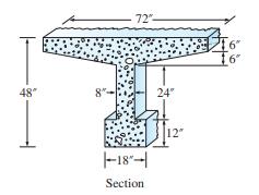
Determine the deadweight of a 1-ft-long segment of the prestressed, reinforced concrete tee-beam whose cross section is shown in Figure P2.1. Beam is constructed with lightweight concrete which weighs \(120 \mathrm{lbs} / \mathrm{ft}^{3}\). 48 8"- 72"- 18- Section 24 12" 6" 16"
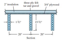
Determine the deadweight of a 1 -ft-long segment of a typical 20-in-wide unit of a roof supported on a nominal \(2 \times 16\) in. southern pine beam (the actual dimensions are \(\frac{1}{2} \mathrm{in}\). smaller). The \(\frac{3}{4}\)-in. plywood weighs \(3 \mathrm{lb} / \mathrm{ft}^{2}\). 2"
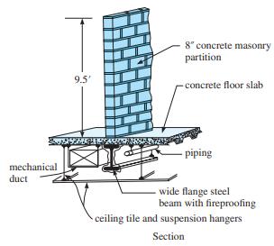
A wide flange steel beam shown in Figure \(P 2.3\) supports a permanent concrete masonry wall, floor slab, architectural finishes, mechanical and electrical systems. Determine the uniform dead load in kips per linear foot acting on the beam. The wall is 9.5 -ft high, non-load bearing and laterally
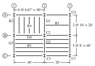
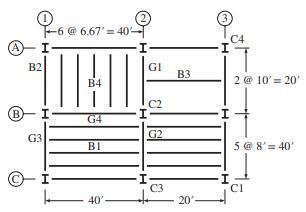
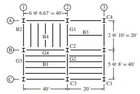
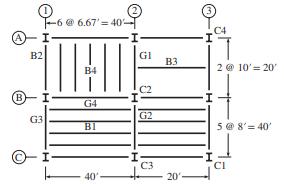
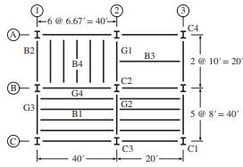
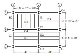
Consider the floor plan shown in Figure P2.4. Compute the tributary areas for(a)(a) floor beam B1, (b) floor beam B2,(c) girder G1,(d) girder G2,(e) corner column C1C1,((f)(f) interior column C2C2. B B2 G3 -6 @ 6.67' = 40- B4 G4 Bl 40'- I GI C2 G2 C3 B3 C4 2 @ 10' = 20' 5 @ 8' 40' CI
Refer to Figure P2.4 for the floor plan. Calculate the tributary areas for (a) floor beam B3, (b) floor beam B4, (c) girder G3, (d) girder G4, (e) edge column C3,(f) corner column C4.Figure P2.4 (B) B2 G3 -6 @ 6.67=40- B4 G4 Bl 40' I GI C2 G2 C3 B3 C4 2 @ 10' 20' 5 @ 8'=40' CI
The uniformly distributed live load on the floor plan in Figure P2.4 is 60lb/ft260lb/ft2. Establish the loading for members (a) floor beam B1,(b) floor beam B2,(c) girder G1G1,(d)(d) girder G2. Consider the live load reduction if permitted by the ASCE standard.Figure P2.4 (B) B2 -6 @ 6.67' 40- 5 @
The uniformly distributed live load on the floor plan in Figure P2.4 is \(60 \mathrm{lb} / \mathrm{ft}^{2}\). Establish the loading for members ( \(a\) ) floor beam \(\mathrm{B} 3\),(b) floor beam B4,(c) girder G3, and girder G4. Consider the live load reduction if permitted by the ASCE
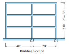
The building section associated with the floor plan in Figure P2.4 is shown in Figure P2.8. Assume a live load of \(60 \mathrm{lb} / \mathrm{ft}^{2}\) on all three floors. Calculate the axial forces produced by the live load in column \(\mathrm{C} 2\) in the third and first stories. Consider any
The building section associated with the floor plan in Figure P2.4 is shown in Figure P2.7. Assume a live load of \(60 \mathrm{lb} / \mathrm{ft}^{2}\) on all three floors. Calculate the axial forces produced by the live load in column \(\mathrm{C} 3\) in the third and first stories. Consider any
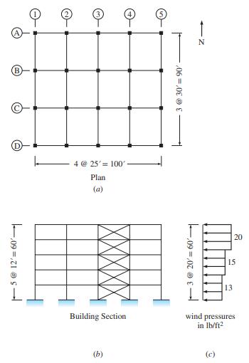
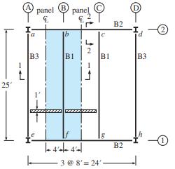
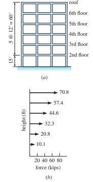
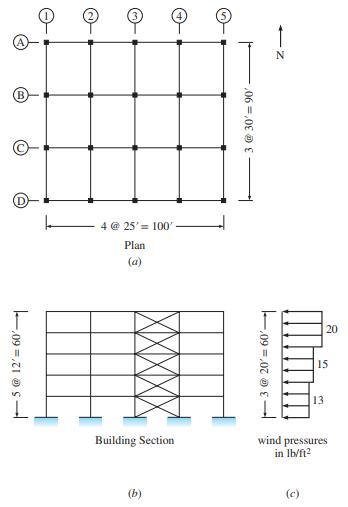
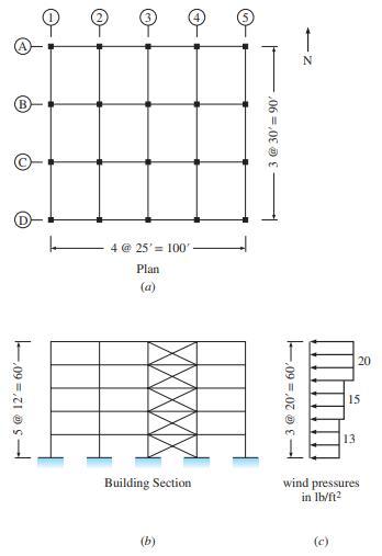
A five-story building is shown in Figure P2.10. Following the ASCE standard, the wind pressure along the height on the windward side has been established as shown in Figure P2.10(c). (a) Considering the windward pressure in the east-west direction, use the tributary area concept to compute the
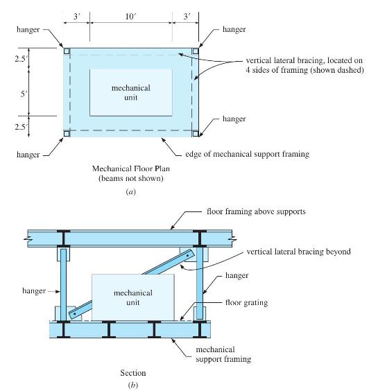
A mechanical support framing system is shown in Figure P2.11. The framing consists of steel floor grating over steel beams and entirely supported by four tension hangers that are connected to floor framing above it. It supports light machinery with an operating weight of \(4000 \mathrm{lbs}\),
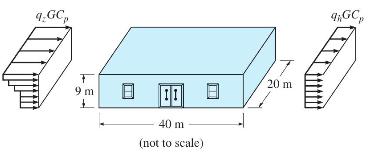
The dimensions of a 9-m-high warehouse are shown in Figure P2.12. The windward and leeward wind pressure profiles in the long direction of the warehouse are also shown. Establish the wind forces based on the following information: basic wind speed \(=40 \mathrm{~m} / \mathrm{s}\), wind exposure
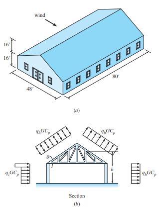
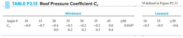
The dimensions of an enclosed gabled building are shown in Figure P2.13a. The external pressures for the wind load perpendicular to the ridge of the building are shown in Figure P2.13b. Note that the wind pressure can act toward or away from the windward roof surface. For the particular building
Establish the wind pressures on the building in Problem P2.13 when the windward roof is subjected to an uplift wind force.Problem P2.13The dimensions of an enclosed gabled building are shown in Figure P2.13a. The external pressures for the wind load perpendicular to the ridge of the building are
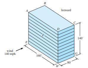
(a) Determine the wind pressure distribution on the four sides of the 10-story hospital shown in Figure P2.15. The building is located near the Georgia coast where the wind velocity contour map in the ASCE Standard specifies a design wind speed of \(140 \mathrm{mph}\). The building, located on
Consider the five-story building shown in Figure P2.10. The average weights of the floor and roof are \(90 \mathrm{lb} / \mathrm{ft}^{2}\) and \(70 \mathrm{lb} / \mathrm{ft}^{2}\), respectively. The values of \(S_{D S}\) and \(S_{D 1}\) are equal to \(0.9 g\) and \(0.4 g\), respectively. Since
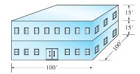
(a) A two-story hospital facility shown in Figure P2.18 is being designed in New York with a basic wind speed of \(90 \mathrm{mi} / \mathrm{h}\) and wind exposure \(D\). The importance factor \(I\) is 1.15 and \(K_{z}=1.0\). Use the simplified procedure to determine the design wind load, base
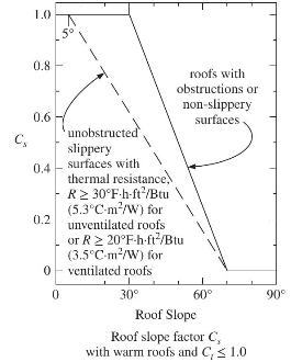
In the gabled roof structure shown in Figure P2.13, determine the sloped roof snow load \(P_{s}\). The building is heated and is located in a windy area in Boston. Its roof consists of asphalt shingles. The building is used for a manufacturing facility, placing it in a type II occupancy category.
A beam that is part of a rigid frame has end moments and mid-span moments for dead, live, and earthquake loads shown below. Determine the governing load combination for both negative and positive moments at the ends and mid-span of the beam. Earthquake load can act in either direction, generating
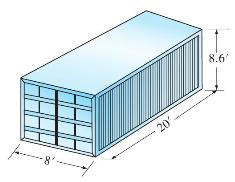
Calculate the vertical hydrostatic load on the 5100-lb empty shipping container in Figure P2.19 subjected to a tsunami inundation height of \(3^{\prime}\). Assuming the container is water-tight, will the tsunami wave be capable of carrying away the container as debris?Figure P2.19 --8- 20' 8.6'
Consider the building in Figure P2.22, which has a width into the page of \(35 \mathrm{ft}\). Maximum inundation height, \(h_{\text {max }}\), and flow velocity, \(u_{\max }\), have been determined as \(33 \mathrm{ft}\) and \(20 \mathrm{ft} / \mathrm{sec}\), respectively. Calculate the hydrodynamic
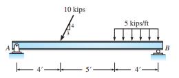
Determine the reactions of structure 10 kips 5 kips/ft 4' B
Determine the reactions of structure 15 kip. ft 5 5' B D 12] E 8 kips 6 kips 10'
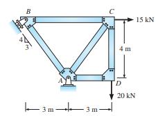
Determine the reactions of structure B -3m- .3m 4m D 20 kN 15 KN
Determine the reactions of structure 1.2 kips/ft B A 18k 12'- D 9
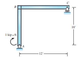
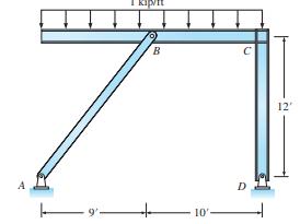
Determine the reactions of structure BO 1 kip. ft 12' 10'
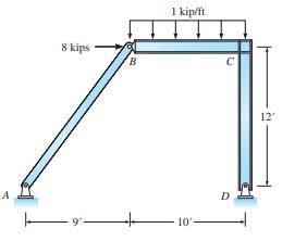
Determine the reactions of structure T 8 kips B 1 kip/ft 10- 12'
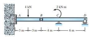
The support at A prevents rotation and horizontal displacement but permits vertical displacement. The shear plate at B is assumed to act as a hinge. Determine the moment at A and the reactions at C and D. A 4 kN B -3m-4-3m- 2 kN-m -3m-4m- 6 m
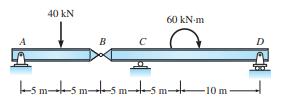
Determine the reactions at all supports and the force transmitted through the hinge at B. A 40 KN B C 60 kN-m sms m5 m-5 m-10 m-
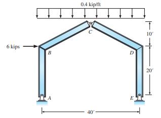
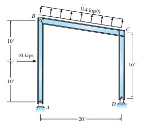
Determine the reactions for each structure. All dimensions are measured from the centerlines of members. 6 kips B 0.4 kip/ft 40' D E T 10' 20'
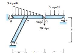
Determine the reactions for each structure. All dimensions are measured from the centerlines of members. 9 kips/ft B 7 5 kips/ft hinge D 20 kips 466 E 8"
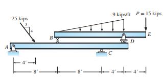
Determine the reactions for each structure. All dimensions are measured from the centerlines of members. 25 kips 4 8' B 9 kips/ft P = 15 kips C D 8 44 | E
Determine all reactions. The pin joint at B can be treated as a hinge. 9' B 10' C D 12'
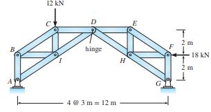
Determine all reactions. The pin joint at D acts as a hinge. 12 kN hinge 4 @ 3m=12m H E T 2 m 18 kN 2 m
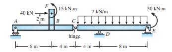
Determine the reactions at all supports and the force transmitted through the hinge at C. A F 40 kN T 2m -6m- 15 kN-m B hinge 2 kN/m 4m4m- D 8 m 30 kN/m
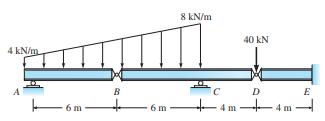
Determine the reactions at supports A, C, and E. 4 kN/m 8 kN/m B C 40 KN D E
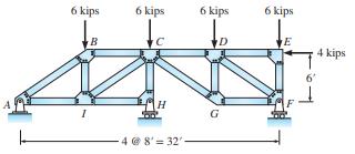
Determine all reactions. Joint C can be assumed to act as a hinge. 6 kips I B 6 kips H 4 @ 8' 32'- 6 kips D G 6 kips E 4 kips
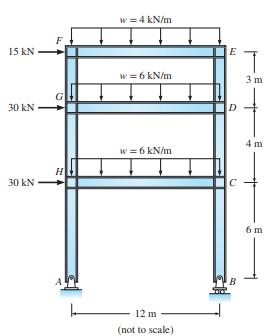
Determine all reactions. The uniform load on all girders extends to the centerlines of the columns. 15 kN 30 kN 30 kN H w = 4 kN/m w = 6 kN/m w = 6 kN/m 12 m (not to scale) E D C bo T 3 m 4 m 6m
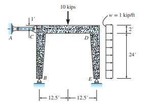
The bent frame BCDE in figure P3.18 is laterally braced by member AC, which acts like a link. Determine reactions at A, B, and E. 10 kips D embuang E |--12.512.5- w = 1 kip/ft 24
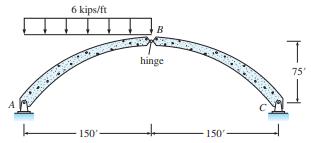
Determine all reactions. 6 kips/ft 150 B hinge 150- T 75'
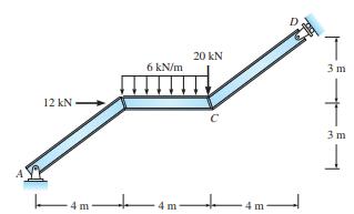
Determine all reactions. 12 kN-> -4m- 6 kN/m 20 KN -4m- + 4 m T 3 m 3 m 1
Determine all reactions. 10' 10' B 10 kips 0.4 kip/ft 20 16'
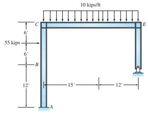
Determine all reactions. The pin joint at E acts as a hinge. H 55 kips 6 12' B -15' 10 kips/ft 12 E
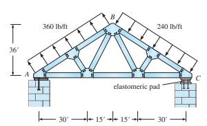
The roof truss is bolted to a reinforced masonry pier at A and connected to an elastomeric pad at C. The pad, which can apply vertical restraint in either direction but no horizontal restraint, can be treated as a roller. The support at A can be treated as a pin. Compute the reactions at supports A
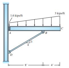
The clip angle connecting the beam’s web at A to the column may be assumed equivalent to a pin support. Assume member BD acts as an axially loaded pin-end compression strut. Compute the reactions at points A and D. 1.6 kips/ft A D 8" B 3 kips/ft -4-
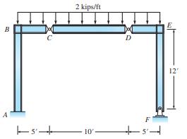
Compute all reactions. B A s 2 kips/ft 10' D -5- E 12"
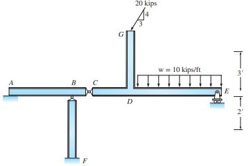
Compute the reactions at supports A, E, and F. A B F D 20 kips w = 10 kips/ft E 3' T 2
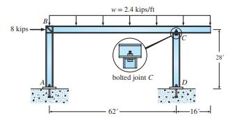
The baseplates at the bottoms of the columns are connected to the foundations at points A and D by bolts and may be assumed to act as pin supports. Joint B is rigid. At C where the bottom flange of the girder is bolted to a cap plate welded to the end of the column, the joint can be assumed to act
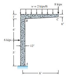
Draw free-body diagrams of column AB and beam BC and joint B by passing cutting planes through the rigid frame an infinitesimal distance above support A and to the right and immediately below joint B. Evaluate the internal forces on each free body. 6 kips 5' B w = 2 kips/ft 12" 8 kips 6
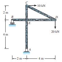
The frame is composed of members connected by frictionless pins. Draw free-body diagrams of each member and determine the forces applied by the pins to the members. T 2m 4 m B -2m- E S 10 kN 4 m- D 20 KN
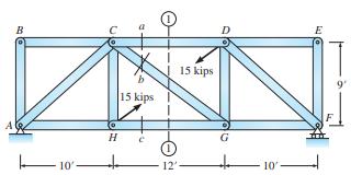
The truss in Figure P3.30 is composed of pin jointed members that carry only axial load. Determine the forces in members, a, b, and c by passing vertical through the center of the truss. A B 10' 15 kips H + 12' 15 kips 10- E 9'
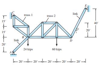
(a) In Figure P3.31 trusses 1 and 2 are stable elements that can be treated as rigid bodies. Compute all reactions. (b) Draw free-body diagrams of each truss and evaluate the forces applied to the trusses at joints C, B, and D. Linna 15' 15' 20' L A link truss 1 B 24 kips truss 2 60 kips D link
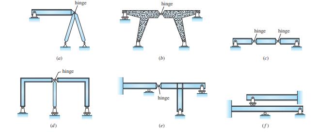
Classify the structures in Figures P3.32. Indicate if stable or unstable. If unstable, indicate the reason. If the structure is stable, indicate if determinate or indeterminate. If indeterminate, specify the degree. (a) hinge (d) (b) hinge + O hinge (c) link ()
Classify the structures in Figures P3.33. Indicate if stable or unstable. If unstable, indicate the reason. If the structure is stable, indicate if determinate or indeterminate. If indeterminate, specify the degree. (a) hinge S hinge E hinge T R hinge O hinge (c) (f) hinge
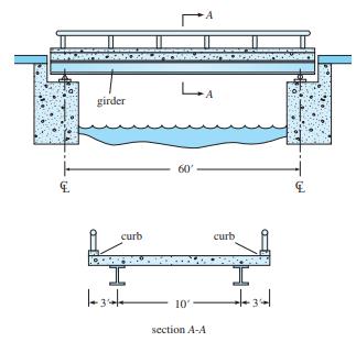
Practical application: A one-lane bridge consists of a 10-in.-thick, 16-ft-wide reinforced concrete slab supported on two steel girders spaced 10 ft apart. The girders are 62-ft long and weigh 400 lb/ft. The bridge is to be de signed for a uniform live load of 700 lb/ft acting over the entire
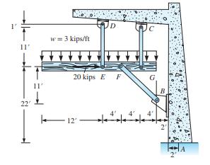
A timber member supported by three steel links to a concrete frame has to carry the loads shown in Figure P3.35. (a) Calculate the reactions at support A. (b) Determine the axial forces in all links. Indicate if each link is in compression or tension. 11' 22' 11' w = 3 kips/ft D 20 kips E F -12 12
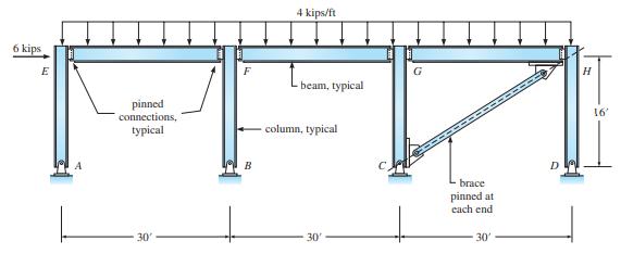
The three bay, one-story frame consists of beams pin connected to columns and column bases pinned to the foundation in Figure P3.36. The diagonal brace member CH is pinned at each end. Determine the reactions at A, B, C, and D and calculate the force in the brace. 6 kips E pinned connections,
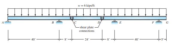
The multispan girder in Figure P3.37 has two shear plate connections that act as hinges at C and D. The midspan girder CD is simply supported on the cantilevered ends of the left and right girders. Determine the forces in the hinges and the reactions at supports A, B, E, and F. 40' w = 6 kips/ft
Showing 500 - 600
of 570
1
2
3
4
5
6
Step by Step Answers
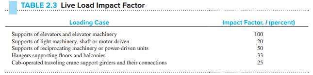

![15 kip. ft 5 5' B D 12] E 8 kips 6 kips 10'](https://dsd5zvtm8ll6.cloudfront.net/images/question_images/1706/1/0/2/36065b10e58d82d01706102359434.jpg)