New Semester
Started
Get
50% OFF
Study Help!
--h --m --s
Claim Now
Question Answers
Textbooks
Find textbooks, questions and answers
Oops, something went wrong!
Change your search query and then try again
S
Books
FREE
Study Help
Expert Questions
Accounting
General Management
Mathematics
Finance
Organizational Behaviour
Law
Physics
Operating System
Management Leadership
Sociology
Programming
Marketing
Database
Computer Network
Economics
Textbooks Solutions
Accounting
Managerial Accounting
Management Leadership
Cost Accounting
Statistics
Business Law
Corporate Finance
Finance
Economics
Auditing
Tutors
Online Tutors
Find a Tutor
Hire a Tutor
Become a Tutor
AI Tutor
AI Study Planner
NEW
Sell Books
Search
Search
Sign In
Register
study help
engineering
fundamentals of structural analysis
Fundamentals Of Structural Analysis 5th Edition Kenneth Leet, Chia-Ming Uang, Joel Lanning - Solutions
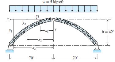
Establish the shape of the funicular arch for the uniform loading acting on the three-hinged arch in Figure 6.18a. To achieve economy, the arch is tapered along its length. Determine the minimum cross sectional area at three locations (x1 = 17.5 ft, x2 = 35 ft, and x3 = 52.5 ft) if the maximum
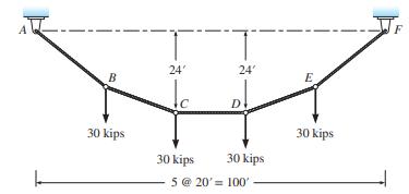
Determine the reactions at the supports, the magnitude of the cable sag at joints \(B\) and \(E\), the magnitude of the tension force in each segment of the cable, and the total length of the cable in Figure P6.1. A B 30 kips 24' Jo 30 kips 24' D 30 kips 5 @ 20' = 100' E 30 kips F
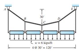
The cable in Figure P6.2 supports four simply supported girders uniformly loaded with \(6 \mathrm{kips} / \mathrm{ft}\). (a) Determine the minimum required area of the main cable \(A B C D E\) if the allowable stress is \(60 \mathrm{kips} / \mathrm{in} .^{2}\). (b) Determine the cable sag at point
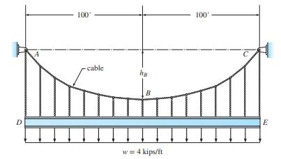
The cable in Figure P6.3 supports girder \(D E\) uniformly loaded with \(4 \mathrm{kips} / \mathrm{ft}\). The supporting hangers are closely spaced, generating a smooth curved cable. Determine the support reactions at \(A\) and \(C\). If the maximum tensile force in the cable cannot exceed 600
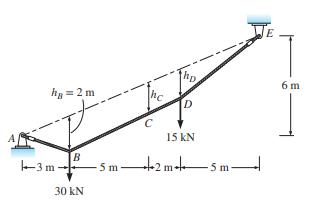
(a) Determine the reactions at supports \(A\) and \(E\) and the maximum tension in the cable in Figure P6.4.(b) Establish the cable sag at points \(C\) and \(D\). ha = 2m -3m- B 30 kN 5m D 15 kN +2m-45m E 6 m
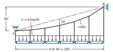
Compute the support reactions and the maximum tension in the main cable in Figure P6.5. The hangers can be assumed to provide a simple support for the suspended beams. 80' A w = 6 kips/ft 20 6 @ 40' 240' cable B
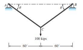
What value of \(\theta\) is associated with the minimum volume of cable material required to support the 100-kip load in Figure P6.6? The allowable stress in the cable is 150 kips/in. \({ }^{2}\). 60' C 100 kips 60 0 B
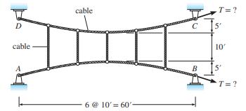
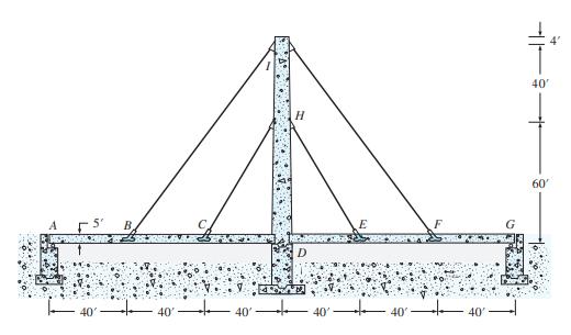
The cables in Figure P6.7 have been dimensioned so that a 3-kip tension force develops in each vertical strand when the main cables are tensioned. What value of jacking force \(T\) must be applied at supports \(B\) and \(C\) to tension the system? D cable A cable 6 @ 10' 60' C T= ? 5' 10' 5' T=?
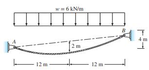
Compute the support reactions and the maximum tension in the cable in Figure P6.8. 12 m w = 6 kN/m 2 m + 12 m- B DE 4 m +
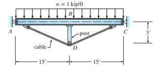
A uniformly distributed load on beam \(A B C\) in Figure P6.9 causes it to sag. To counteract this sag, a cable and post are added beneath the beam. The cable is tensioned until the force in the post causes a moment equal in magnitude, but opposite in direction, to the moment in the beam. Determine
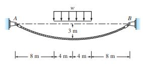
Compute the support reactions and the maximum value of \(w\) if the allowable tension force in the cable in Figure P6.10 is \(200 \mathrm{kN}\). W 3 m 8 m4m 4 m 8 m B
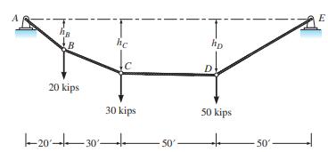
The cable in Figure P6.11 is capable of carrying a tensile load of \(180 \mathrm{kips}\) and the pin supports are capable of providing a horizontal reaction of 150 kips. Determine the shape of the cable subjected to the loading shown. ha B 20 kips he 30 kips -20-30- 50' hp D 50 kips 50' E
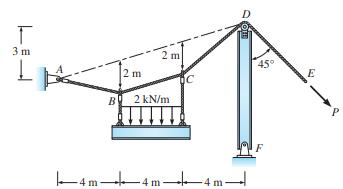
A cable ABCD is pulled at end E by a force P (Figure P6.12). The cable is supported at point D by a rigid member DF. Compute the force P that produces a sag of 2 m at points B and C. The horizontal reaction at support F is zero. Compute the vertical reaction at F. T 3 m L -- B 2 m 2 kN/m -4m-l -4m-
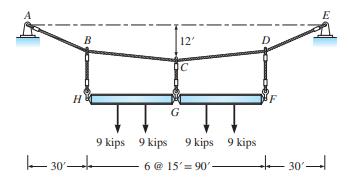
Compute the support reactions and the maximum tension in the cable in Figure P6.13. The sag at midspan is \(12 \mathrm{ft}\). Each hanger can be assumed to provide a simple support for the suspended beam. Determine the sag at points \(B\) and \(D\). 30' B H G 12' C 9 kips 9 kips 9 kips 9 kips 6 @
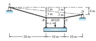
Determine the location of the \(40-\mathrm{kN}\) load such that sags at points \(B\) and \(C\) in Figure P6.14 are \(3 \mathrm{~m}\) and \(2 \mathrm{~m}\), respectively. Determine the maximum tension in the cable and the reactions at supports \(A\) and \(D\). 20 m- B 2 m 3 m 3 m 2 m 40 KN 10m-10m D
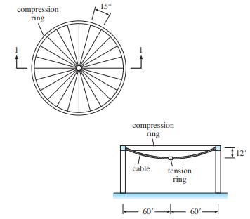
The cable-supported roof for a summer theater, shown in Figure P6.15, is composed of 24 equally spaced cables that span from a tension ring at the center to a compression ring on the perimeter. The tension ring lies 12 ft below the compression ring. The roof weighs 25 lb/ft2 based on the horizontal
Computer study of a cable-stayed bridge. The deck and tower making up the two-span, cable-stayed bridge in Figure P6.16 are constructed of reinforced concrete. The cross section of the bridge is constant with an area of 15 ft2 and a moment of inertia of 19 ft4 . The dead weight of the girders is 4
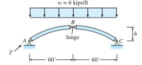
For the parabolic arch in Figure P6.17, plot the variation of the thrust \(T\) at support \(A\) for values of \(h=12\), \(24,36,48\), and \(60 \mathrm{ft}\). T w = 6 kips/ft 60'- B hinge 60 h
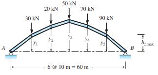
For the arch and loading in Figure P6.18, compute the reactions and determine the height of each point. The maximum height permitted at any point along the arch, \(h_{z \max }\), is \(20 \mathrm{~m}\). 30 kN V1 20 KN 50 KN 3 70 kN LLL 6 @ 10 m 60 m 90 KN Y5 B T h.. max
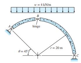
Determine the reactions at supports \(A\) and \(C\) of the three-hinged circular arch. 0=45% w = 4 kN/m B hinge r = 20 m
For the arch shown in Figure P6.20, the thrust force exceeded the abutment's lateral support capacity, which is represented by a roller at \(C\). Load \(P\) was removed temporarily and tension \(\operatorname{rod} A C\) was added. If the maximum compression in members \(A B\) and \(B C\) will be
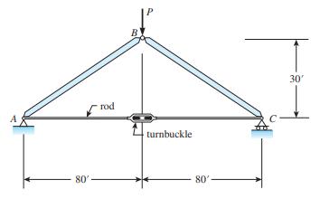
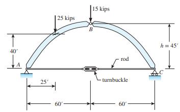
The arch shown in Figure P6.21 has a pin support at \(A\) and a roller at \(C\). A tension rod connects \(A\) and \(C\). Determine the reactions at \(A\) and \(C\) and the tension in \(\operatorname{rod} A C\). 40' 25' 25 kips 60' 15 kips B rod -turnbuckle 60' h = 45'
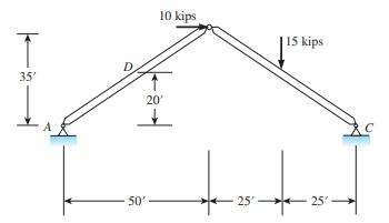
For the three-hinged arch shown in Figure P6.22, compute the reactions at \(A\) and \(C\). Determine the axial force, shear, and moment at \(D\). T 35' 10 kips V 20' 50' 25' 15 kips 25- z c
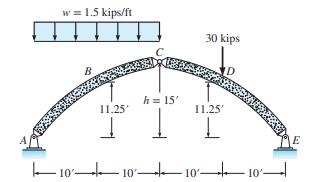
Compute the reactions at supports \(A\) and \(E\) of the three-hinged parabolic arch in Figure P6.23. Next compute the shear, axial load, and moment at points \(B\) and \(D\), located at the quarter points. w = 1.5 kips/ft B 11.25' I h = 15' 1 30 kips -101010 ID 11.25' L 10'- E
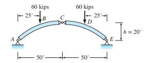
The three-hinged parabolic arch in Figure P6.24 supports 60-kip load at the quarter points. Determine the shear, axial load, and moment on sections an infinitesimal distance to the left and right of the loads. The equation for the arch axis is \(y=4 h x^{2} / L^{2}\). 60 kips 25-B C Dod 60 kips
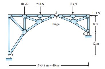
Compute the support reactions for the arch in Figure P6.25. You will need two moment equations: Consider the entire free body for one, and a free body of the portion of truss to either the left or right of the hinge at \(B\). 10 KN 20 KN hinge 5 @ 8m = 40 m 30 kN 18 kN 8 m 12 m
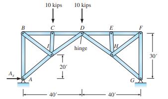
Compute the horizontal reaction at \(A\) of the arch in Figure P6.26. A B 10 kips T 20 T 40' 10 kips hinge 40' 30'
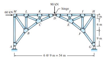
(a) Determine the reactions and all bar forces of the three-hinged, trussed arch in Figure P6.27 for the following cases:Case A: Only the \(90-\mathrm{kN}\) force at joint \(D\) acts.Case B: Both the \(90-\mathrm{kN}\) and \(60-\mathrm{kN}\) forces at joints \(D\) and \(M\) act.(b) Determine the
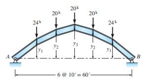
Establish the funicular arch for the system of loads in Figure P6.28, if the maximum allowable compressive force in the arch is 85 kips. A 24k Y 20k Y2 20k 20k Y3 32 1.1 6 @ 10' 60'- 24k 3 B
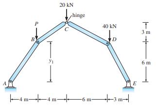
Determine the load \(P\) such that all the members in the three-hinged arch in Figure P6.29 are in pure compression. What is the value of \(y_{1}\) ? P 31 20 KN hinge 40 kN E | |4 m4 m+ -6 m|3 m|| T 3 m 6m
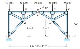
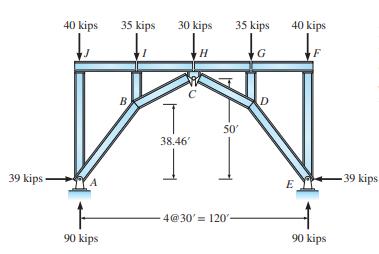
If the arch rib \(A B C D E\) in Figure \(\mathrm{P} 6.30\) is to be funicular for the dead loads shown at the top joints, establish the elevation of the lower chord joints at \(B\) and \(D\). 40 kips 35 kips B h = ? 30 kips hinge 35 kips h = ? I 4 @ 30' = 120' 40 kips F E 50'
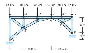
For the arch rib to be funicular for the dead loads shown, establish the elevation of the lower chord joints \(B, C\), and \(E\). 15 kN L 30 kN K B 30 kN 3@8m J 30 kN 30 kN 15 kN D E H +2@6m G T 8 m 4 m
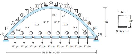
Computer study of a two-hinged arch. The objective is to establish the difference in response of a parabolic arch to (1) uniformly distributed loads and (2) a single concentrated load.(a) The arch in Figure P6.32 supports a roadway consisting of simply supported beams connected to the arch by
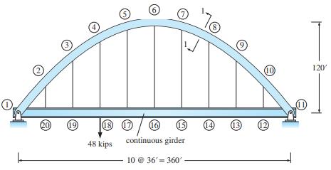
Computer study of arch with a continuous floor girder. Repeat part (b) in problem P6.33 if a continuous girder with A = 102.5 in2 and I = 40,087 in.4 , as shown in Figure P6.33, is provided to support the floor system. For both the girder and the arch, determine all forces acting on the arch joints
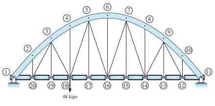
To reduce the vertical displacement of the roadway floor system of the arch produced by the 48-kip load at joint 18, diagonal cables of 2 in. in diameter are added as shown in Figure P6.34. For this configuration, determine the vertical displacement of all the floor system joints. Plotting to scale
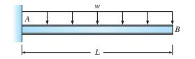
Derive the equations for slope and deflection for the beam in Figure P7.1.Compare the deflection at \(B\) with the deflection at midspan. A W L B
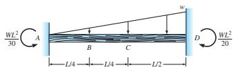
Derive the equations for slope and deflection of the beam shown in Figure P7.2.Assume the moment reactions at each fixed end are as shown. Compute the deflections at points \(B\) and \(C\). WE CA WL 30 C UA- 24 24+ B -1/2- DW WL 20
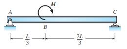
Derive the equations for slope and deflection for the beam in Figure P7.3.Compute the maximum deflection. Hint: Maximum deflection occurs at point of zero slope. M A L B
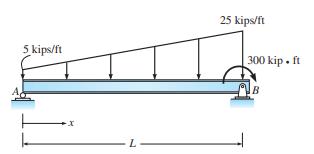
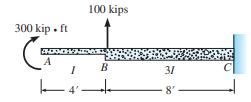
Derive the equations for slope and deflection for the beam in Figure P7.4.If \(E=29,000 \mathrm{ksi}, I=50 \mathrm{in} .{ }^{4}\), and \(L=10 \mathrm{ft}\), compute the values of slope and deflection at \(x=\frac{3}{4} L\). 5 kips/ft -X L 25 kips/ft 300 kip. ft B
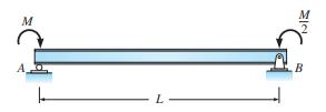
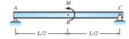
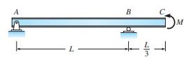
Establish the equations for slope and deflection for the beam in Figure P7.5.Evaluate the magnitude of the slope at each support. Express answer in terms of \(E I\). A L/2 M B L/2 C
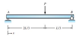
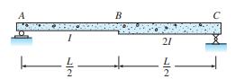
Derive the equations for slope and deflection for the beam in Figure P7.6.Determine the slope at each support and the value of the deflection at midspan. Hint: It has been determined that the maximum deflection occurs at \(x=0.544 L\) such that the slope is zero there. 2L/3 P L/3- B
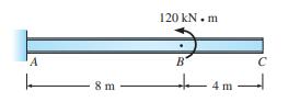
Compute the slope and deflection at points \(B\) and \(C\) in Figure P7.7. A 8 m 120 kN.m B 4 m
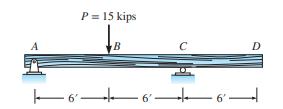
(a) Compute the slopes at \(A\) and \(C\) and the deflection at \(D\) in Figure P7.8.(b) Locate and compute the magnitude of the maximum deflection. A P = 15 kips B 66' 6' D
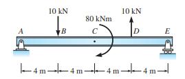
Compute the slopes at \(A\) and \(C\) and the deflection at \(B\) for the beam in Figure P7.9. A 10 KN B 80 kNm C 10 kN D E 4m4m4m4m- L
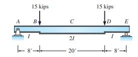
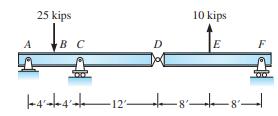
(a) Compute the slope at \(A\) and the deflection at midspan in Figure P7.10.(b) If the deflection at midspan is not to exceed \(1.2 \mathrm{in}\)., what is the minimum required value of \(I\) ? \(E=29,000 \mathrm{kips} / \mathrm{in}^{2}\). A 15 kips B C 21 20' 15 kips D E
(a) Find the slope and deflection at \(A\) in Figure P7.11.(b) Determine the location and the magnitude of the maximum deflection in span \(B C\). 10 kips 1 6' B 21 12' 6 10 kips D
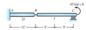
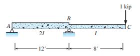
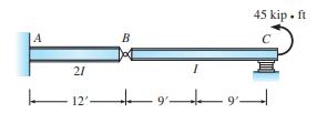
Compute the slopes of the beam in Figure P7.12 on each side of the hinge at \(B\), the deflection of the hinge, and the maximum deflection in span \(B C\). The elastomeric support at \(C\) acts as a roller. A 21 B I 9' 12 45 kip. ft 9
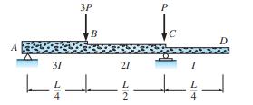
Compute the slope at support \(A\) and the deflection at point \(B\). Express the answer in terms of \(E I\). 3P D L 31+ 3 44
Determine the slopes at \(A\) and \(B\) and the deflection at \(C\) in Figure P7.14.Express answers in terms of \(M\), \(E, I\), and \(L\). A L B 2/m SM -
Determine the slope and deflection of point \(C\) in Figure P7.15.Draw moment curves by parts. A 3 m 30 kN B 9 kN/m 2 m
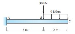
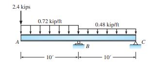
The roof beam of a building is subjected to the loading shown in Figure P7.16.If a \(3 / 8\)-in. deflection is permitted at the cantilever end before the ceiling and roofing materials would be damaged, calculate the required moment of inertia for the beam. Use \(E=29,000 \mathrm{ksi}\). 2.4 kips A
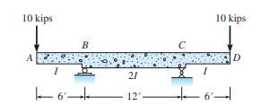
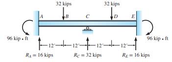
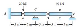
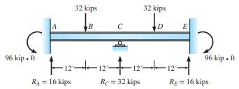
Compute the slope and deflection under the 32-kip load at \(B\) and \(D\). Reactions are given. \(I=510 \mathrm{in}^{4}\) and \(E=29,000 \mathrm{kips} / \mathrm{in} .^{2}\). Sketch the deflected shape. 96 kip. ft 32 kips R = 16 kips B C 32 kips D E 12121212 Rc = 32 kips 96 kip. ft Rg = 16 kips
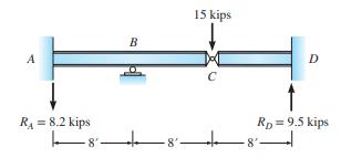
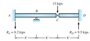
The vertical reactions at supports \(A\) and \(D\) of the indeterminate beam in Figure P7.18 are given. Compute the slope at \(B\) and the deflection at \(C\). \(E I\) is constant. A R = 8.2 kips 8 B 15 kips C D RD = 9.5 kips 8' 4
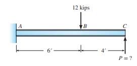
What value of force \(P\) is required at \(C\) in Figure P7.19 if the vertical deflection at \(C\) is to be zero? 6' 12 kips B 4' P = ?
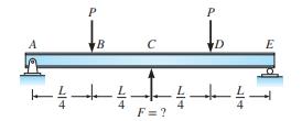
If the vertical deflection of the beam at midspan (i.e., point \(C\) ) is to be zero, determine the magnitude of force \(F\). \(E I\) is constant. Express \(F\) in terms of \(P\) and \(E I\). B ---++- F=? P D ++
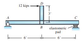
Compute the horizontal deflection at \(D\) and vertical deflection at \(B\) in Figure P7.21.The elastomeric pad at \(C\) acts as a roller. A 12 kips. 6' D B 3' elastomeric pad 6' C
Compute the horizontal and vertical deflections at \(C\) of the frame in Figure P7.22.EI is constant. 20 kips B 12'
Compute the horizontal and vertical deflections at \(C\) of the frame in Figure P7.23.EI is constant. 20 kips B A 14- 8'
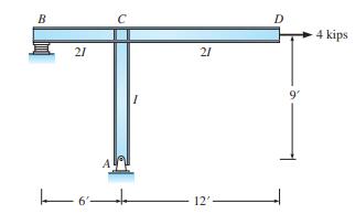
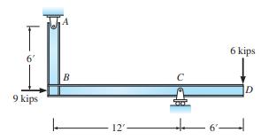
The moment of inertia of the girder in Figure P7.24 is twice that of the column. If the vertical deflection at \(D\) is not to exceed \(1 \mathrm{in}\). and if the horizontal deflection at \(C\) is not to exceed \(0.5 \mathrm{in}\)., what is the minimum required value of the moment of inertia?
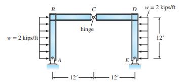
Compute the vertical displacement of the hinge at \(C\) in Figure P7.25.EI is constant. w = 2 kips/ft B 12 hinge -12'- E Dw=2 kips/ft 12'
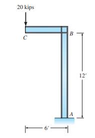
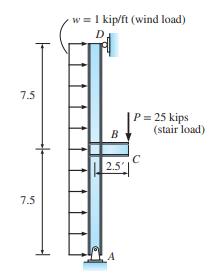
The loading acting on a column that supports a stair and exterior veneer is shown in Figure P7.26.Determine the required moment of inertia for the column such that the maximum lateral deflection does not exceed \(1 / 4\) in., a criterion set by the veneer manufacturer. Use \(E=29,000\) kips/in. \({
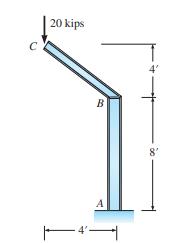
Compute the slope at \(A\) and the horizontal and vertical components of deflection at point \(D\) in Figure P7.27. 6' 9 kips B 12' 6' 6 kips D
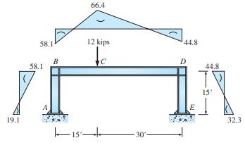
Compute the horizontal displacement of joint \(B\) in Figure P7.28.The moment diagram produced by the 12-kip load is given. The base of the columns at points \(A\) and \(E\) may be treated as fixed supports. Begin by sketching the deflected shape, using the moment diagrams to establish the
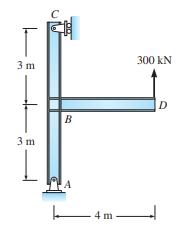
Compute the rotation at \(B\) and the vertical deflection at \(D\). Given: \(E=200 \mathrm{GPa}, I_{A C}=400=10^{6} \mathrm{~mm}^{4}\), and \(I_{B D}=800 \times 10^{6} \mathrm{~mm}^{4}\). T 3 m 3 m. - B -4 m. 300 KN D
The frame shown in Figure P7.30 is loaded by a horizontal load at \(B\). Compute the horizontal displacements at \(B\) and \(D\). For all members \(E=200 \mathrm{GPa}\) and \(I=\) \(500 \times 10^{6} \mathrm{~mm}^{4}\). 100 KN B 12 m D 5m 5m
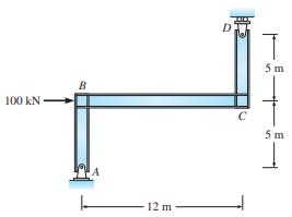
Compute the deflection at the tip of the cantilever beam in Figure P7.31.\(E\) is constant. 300 kip. ft C A I 100 kips B 31 8
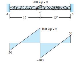
The moment diagram of a fix-ended beam with an external moment of \(200 \mathrm{kip} \cdot \mathrm{ft}\) applied at midspan is shown in Figure P7.32.Determine the maximum vertical deflection and maximum slope and their locations. -50 15' 200 kip. ft B 15'. 100 kip. ft -100 50
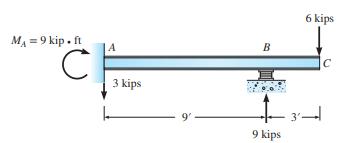
Compute the slope and deflection at point \(C\) and the maximum deflection between \(A\) and \(B\) for the beam in Figure P7.33.The reactions are given, and \(E I\) is constant. The elastomeric pad at \(B\) is equivalent to a roller. M = 9 kip. ft C A 3 kips 9. B 9 kips 6 kips C
Compute the slope at \(A\) and the deflection at \(C\) of the beam in Figure P7.34 due to a unit load at point \(C\). \(E\) is constant. 21 12 B I 8 I kip C
Determine the flexural stiffness of the beam in Figure P7.35 (see Example 7.16 for criteria) for (a) moment applied at \(A\) and (b) moment applied at \(C . E\) is constant. 21 7/2 7/2
Compute the deflection and the slopes on both sides of the hinge at \(B\) in Figure P7.36.\(E I\) is constant. A 20 kN K B 40 kN DE -5m-5m-5m-5m-5m-
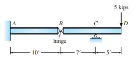
Compute the maximum deflection in span \(B C\) of the beam in Figure P7.37 and the slope on each side of the hinge. A 10- B C 5 kips hinge 7'5' D
Solve Problem P7.11 by the conjugate beam method.Problem P7.11(a) Find the slope and deflection at A in Figure P7.11.(b) Determine the location and the magnitude of the maximum deflection in span BC. 10 kips A R 21 . . 12'. 10 kips D
Solve Problem P7.12 by the conjugate beam method.Problem P7.12Compute the slopes of the beam in Figure P7.12 on each side of the hinge at B, the deflection of the hinge, and the maximum deflection in span BC. The elastomeric support at C acts as a roller. A 21 12' B 9'- 45 kip - ft
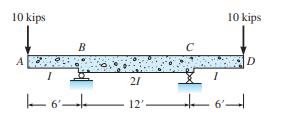
Draw the slope and deflection diagrams for the beam in Figure P7.40.Segment \(A B C D\) has \(2 I\) while segment DEF has \(I\). \(E\) is constant. A 25 kips BC 10 kips E |--4--4-1288'|
Solve Problem P7.17 by the conjugate beam method.Problem P7.17Compute the slope and deflection under the 32-kip load at B and D. Reactions are given. I = 510 in.4 and E = 29,000 kips/in.2 . Sketch the deflected shape. 96 kip. ft A 32 kips R = 16 kips B C 32 kips D 12+12+12-1 Rc = 32 kips E 12 4 Rg
Solve Problem P7.18 by the conjugate beam method.Problem P7.18The vertical reactions at supports A and D of the indeterminate beam in Figure P7.18 are given. Compute the slope at B and the deflection at C. EI is constant. R = 8.2 kips -8 B 15 kips -8 D RD = 9.5 kips
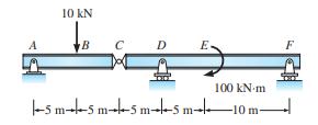
For the beam shown in Figure P7.43, use the conjugate beam method to compute the vertical deflection and the rotation to the left and the right of the hinge at C. Given: E = 200 GPa, IAC = 100 × 106 mm4 , and ICF = 50 × 106 mm4 . A 10 kN B C D E. 100 kN/m -5 m-5 m-5 m-5 m- 10 m-
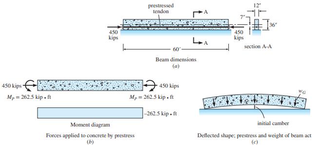
The reinforced concrete girder shown in Figure P7.44a is prestressed by a steel cable that induces a compression force of 450 kips with an eccentricity of 7 in. The external effect of the prestressing is to apply an axial force of 450 kips and equal end moment MP = 262.5 kip ·ft at the ends of the
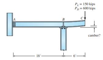
Because of poor foundation conditions, a 30-in. deep steel beam with a cantilever is used to support an exterior building column that carries a dead load of 600 kips and a live load of 150 kips (Figure P7.45). What is the magnitude of the initial camber that should be induced at point C, the tip of
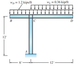
The rigid jointed steel frame with a fixed base at support A has to carry both the dead and live loads shown in Figure P7.46.Both the column and the girder are constructed from the same size members. What is the minimum required moment of inertia of the frame members if the vertical deflection at D
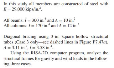
Computer study of the behavior of multistory building frames. The object of this study is to examine the behavior of building frames fabricated with two common types of connections. When open interior spaces and future flexibility of use are prime considerations, building frames can be constructed
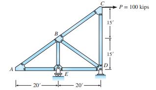
For the truss in Figure P8.1, compute the horizontal and vertical components of displacement of joint \(B\) produced by the 100 -kip load. The area of all bars \(=4 \mathrm{in} .^{2}\), and \(E=24,000\) kips/in. \({ }^{2}\). 20'- B E 20'- 15' 15' pl P = 100 kips
For the truss in Figure P8.1, compute the vertical displacement of joint \(A\) and the horizontal displacement of joint \(C\). Assume all member properties are the same except the areas of \(A E, E D, B D\), and \(B C\) are 8 in. \(^{2}\).
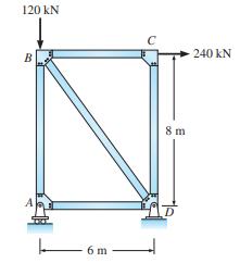
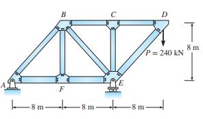
For the truss in Figure P8.3, compute the horizontal and vertical components of the displacement of joint \(C\). The area of all bars \(=2500 \mathrm{~mm}^{2}\), and \(E=200 \mathrm{GPa}\). 120 KN B 6 m 8 m 240 KN
For the truss in Figure P8.4, compute (a) the vertical displacement of joint \(C,(b)\) the horizontal displacement of joint \(C\), and \((c)\) the horizontal displacement of joint \(D\). Members \(A B, B C\), and \(C D\) have area \(=1 \mathrm{in} .^{2}\), and members \(A E, E D, B E\), and \(C E\)
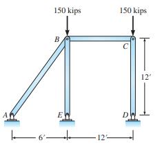
The pin-connected frame in Figure P8.3 is subjected to two vertical loads. Compute the vertical displacement of joint \(B\). Will the frame sway horizontally? If yes, compute the horizontal displacement of joint \(B\). The area of all bars \(=5\) in. \({ }^{2}\), and \(E=29,000\) kips/in. \({
For the pin-connected frame in Figure P8.5, in addition to the vertical loads a lateral load of 30 kips also acts to the right at joint \(B\). Compute the vertical and horizontal displacements at joint \(B\).
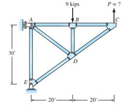
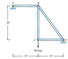
Determine the value of the force \(P\) that must be applied to joint \(C\) of the truss in Figure P8.7 if the vertical deflection at \(C\) is to be zero. The area of all bars \(=1.8 \mathrm{in} .{ }^{2}\), and \(E=30,000\) kips/in. \({ }^{2}\). 30' E 20'- 9 kips B D 20' P = ?
When the truss in Figure P8.8 is loaded, the support at \(E\) displaces 0.6 in. vertically downward and the support at \(A\) moves \(0.4 \mathrm{in}\). to the right. Compute the horizontal and vertical components of displacement of joint \(C\). For all bars the area \(=2\) in. \(^{2}\), and
When the 20-kip load is applied to joint \(B\) of the truss in Figure P8.9, support \(A\) settles vertically downward \(\frac{3}{4}\) in. and displaces \(\frac{1}{2}\) in. horizontally to the right. Determine the vertical displacement of joint \(B\) due to all effects. The area of all bars \(=2
(a) Compute the horizontal displacement of joint \(B\) produced by the \(240-\mathrm{kN}\) load in Figure P8.10.For all bars, area \(=2400 \mathrm{~mm}^{2}\) and \(E=200 \mathrm{GPa}\). (b) Assuming that no load acts, determine the horizontal displacement of joint \(B\) if support \(A\) moves \(20
Determine the horizontal and vertical deflection of joint \(C\) of the truss in Figure P8.11.In addition to the load at joint \(C\), the temperature of member \(B D\) is subject to a temperature increase of \(60^{\circ} \mathrm{F}\). For all bars, \(E=29,000\) kips/ in. \(^{2}, A=4\) in. \({
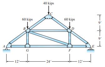
For the truss in Figure P8.12, compute the vertical displacement at joint \(G\). The area of all bars \(=5\) in. \(^{2}\), and \(E=29,000\) kips/in. \({ }^{2}\). 12'- 60kips G 40 kips 24 60 kips F 12'- 9' 9' ||
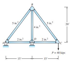
(a) Compute the vertical deflection of joint \(D\) produced by the 30-kip load in Figure P8.13.For all bars, area \(=2 \mathrm{in} .^{2}\), and \(E=9000 \mathrm{kips} / \mathrm{in}^{2}{ }^{2}\). (b) Assume that the truss is not loaded. If bar \(A E\) is fabricated \(\frac{8}{5}\) in. too long, how
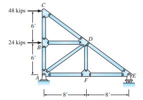
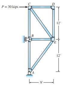
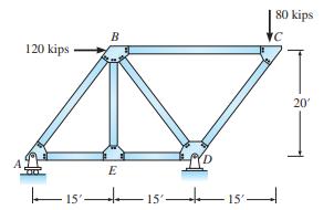
(a) Find the horizontal deflection at joint \(B\) produced by the 40-kip load in Figure P8.14.The area of all bars is shown on the sketch of the truss; \(E=30,000 \mathrm{kips} / \mathrm{in} .{ }^{2}\). (b) To restore joint \(B\) to its initial position in the horizontal direction, how much must
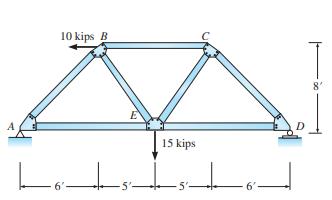
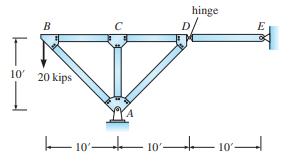
(a) In Figure P8.15 compute the vertical and horizontal components of displacement of joint \(E\) produced by the loads. The area of bars \(A B, B D\), and \(C D=5\) in. \(^{2}\); the area of all other bars \(=3 \mathrm{in} .^{2} . E=30,000 \mathrm{kips} / \mathrm{in} .^{2} .(\mathrm{b})\) If bars
Compute the vertical displacement of the hinge at \(C\) for the funicular loading shown in Figure P8.16.The funicular loading produces direct stress on all sections of the arch. Columns transmit only axial load from the roadway beams to the arch. Also assume that the roadway beams and the columns
Determine the horizontal and vertical deflection of the hinge at point CC of the arch in Figure P8.16 for a single concentrated load of 60 kips applied at joint BB in the vertical direction. 39 kips 40 kips 35 kips 30 kips 35 kips 40 kips B 38.46' 50' D 39 kips E 4@30-120- 90 kips 90 kips
Compute the slope at support \(A\) and the deflection at \(B\) in Figure P8.18.\(E I\) is constant. Express your answer in terms of \(E, I, L\), and \(M\). | 13 B M
Showing 200 - 300
of 570
1
2
3
4
5
6
Step by Step Answers