New Semester
Started
Get
50% OFF
Study Help!
--h --m --s
Claim Now
Question Answers
Textbooks
Find textbooks, questions and answers
Oops, something went wrong!
Change your search query and then try again
S
Books
FREE
Study Help
Expert Questions
Accounting
General Management
Mathematics
Finance
Organizational Behaviour
Law
Physics
Operating System
Management Leadership
Sociology
Programming
Marketing
Database
Computer Network
Economics
Textbooks Solutions
Accounting
Managerial Accounting
Management Leadership
Cost Accounting
Statistics
Business Law
Corporate Finance
Finance
Economics
Auditing
Tutors
Online Tutors
Find a Tutor
Hire a Tutor
Become a Tutor
AI Tutor
AI Study Planner
NEW
Sell Books
Search
Search
Sign In
Register
study help
engineering
fundamentals of structural analysis
Fundamentals Of Structural Analysis 5th Edition Kenneth Leet, Chia-Ming Uang, Joel Lanning - Solutions
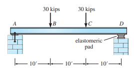
Compute the deflection at midspan and the slope at \(A\) in Figure P8.19.EI is constant. Express the slope in degrees and the deflection in inches. Assume a pin support at \(A\) and a roller at \(D . E=29,000\) kips/in. \({ }^{2}, I=2000\) in. \({ }^{4}\). 10' 30 kips B 10' 30 kips elastomeric pad
(a) Compute the vertical deflection and slope of the cantilever beam at points \(B\) and \(C\) in Figure P8.20.Given: \(E I\) is constant throughout, \(L=12 \mathrm{ft}\), and \(E=\) \(4000 \mathrm{kips} / \mathrm{in} .^{2}\). What is the minimum required value of \(I\) if the deflection of point
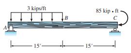
Compute the deflection at \(B\) and the slope at \(C\) in Figure P8.21.Given: \(E I\) is constant. 3 kips/ft 15' B 15'- 85 kip. ft
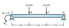
Determine the value of moment that must be applied to the left end of the beam in Figure P8.22 if the slope at \(A\) is to be zero. \(E I\) is constant. Assume rocker at support \(D\) acts as a roller. 0=0 4 M 24 KN B 3m+++ 24 KN c -3m-3m-
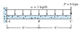
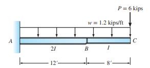
Compute the vertical deflection of point \(C\) in Figure P8.23.Given: \(I=1200\) in. \(^{4}, E=29,000\) kips/in. \({ }^{2}\). A 21 12- w = 1.2 kips/ft B to 1 P = 6 kips 8' C
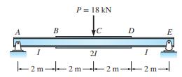
Compute the deflection at midspan of the beam in Figure P8.24.Given: \(I=46 \times 10^{6} \mathrm{~mm}^{4}, E=200 \mathrm{GPa}\). Treat rocker at \(E\) as a roller. B P = 18 kN te D 21 2 m-42 m-42 m-4 E 2m-l
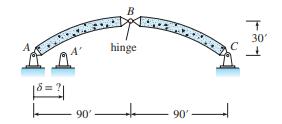
Under the dead load of the arch in Figure P8.25, the hinge at \(B\) is expected to displace 3 in. downward. To eliminate the 3 -in. displacement, the designers will shorten the distance between supports by moving support \(A\) to the right. How far should support \(A\) be moved? 90' 2 B hinge 90' T
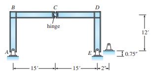
If supports \(A\) and \(E\) in Figure \(\mathrm{P} 8.26\) are constructed \(30 \mathrm{ft}\) and \(2 \mathrm{in}\). apart instead of \(30 \mathrm{ft}\) apart, and if support \(E\) is also 0.75 in. above its specified elevation, determine the vertical and horizontal components of deflections of the
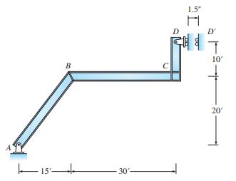
In Figure P8.27 support \(D\) is constructed 1.5 in. to the right of its specified location. Using Bernoulli's principle in Section 8.8, compute (a) the horizontal and vertical components of the displacement of joint \(B\) and \((b)\) the change in slope of member \(B C\). 15% B 30- C 1.5" H 11 00
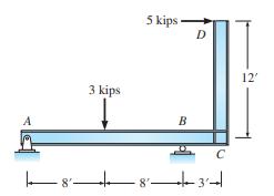
Compute the horizontal and vertical components of deflection at point \(D\) in Figure P8.28.\(E I\) is constant, \(I=120\) in. \(^{4}, E=29,000\) kips/in. \({ }^{2}\). A 3 kips |8| 5 kips B D -83 C 12'
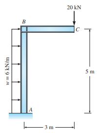
Compute the horizontal and vertical components of the deflection at \(C\) in Figure P8.29.\(E=200 \mathrm{GPa}, A=\) \(25 \times 10^{3} \mathrm{~mm}^{2}\), and \(I=240 \times 10^{6} \mathrm{~mm}^{4}\). w = 6 kN/m B -3m- 20 KN C 5m
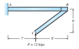
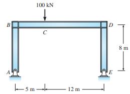
Compute the vertical displacement of joints \(B\) and \(C\) for the frame shown in Figure P8.30.Given: \(I=360\) in. \({ }^{4}, E=30,000 \mathrm{kips} / \mathrm{in} .{ }^{2}\). Consider only flexural deformations. A P = 12 kips 8'- B 6
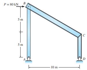
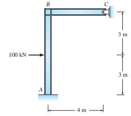
For the steel rigid frame in Figure P8.31, compute the rotation of joint \(B\) and the horizontal displacement of support \(C\). Given: \(E=200 \mathrm{GPa}, A=500 \mathrm{~mm}^{2}\), \(I=200 \times 10^{6} \mathrm{~mm}^{4}\). 3m- 60 KN B 4m 4 m
(a) Compute the slope at \(A\) and the horizontal displacement of joint \(B\) in Figure P8.32.\(E I\) is constant for all members. Consider only bending deformations. Given: \(I=100\) in. \({ }^{4}, E=29,000 \mathrm{kips} / \mathrm{in}^{2}{ }^{2}\). (b) If the horizontal displacement at joint \(B\)
For the frame in Figure P8.33, compute the horizontal and vertical displacements at joint \(B\). Given: \(I=150\) in. \({ }^{4}, E=29,000 \mathrm{kips} / \mathrm{in} .{ }^{2}\). Consider only the flexural deformations. B 10 kips C D 6' | 6 6 66- 6'- T 6' E- 8 1 8'
(a) Compute the vertical displacement of the hinge at \(C\) in Figure P8.34.\(E I\) is constant for all members, \(E=\) \(200 \mathrm{GPa}, I=1800 \times 10^{6} \mathrm{~mm}^{4}\). (b) The designer would like to offset the vertical displacement of the hinge at \(C\) by moving the support \(A\). How
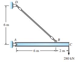
Compute the vertical displacement of point \(C\) for the beam in Figure P8.35.For the beam \(A=5000 \mathrm{~mm}^{2}\), \(I=360 \times 10^{6} \mathrm{~mm}^{4}\), and \(E=200 \mathrm{GPa}\). For the cable \(A=6000 \mathrm{~mm}^{2}\) and \(E=150 \mathrm{GPa}\). 6 m -6m B --- 2m C 280 kN
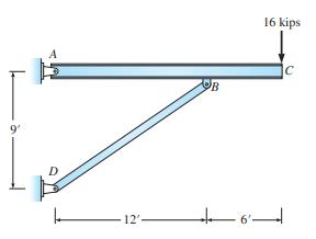
Compute the vertical deflection of joint \(C\) in Figure P8.36.In member \(A B C\) consider only the strain energy associated with bending. Given: \(I_{A C}=340 \mathrm{in} .^{4}\), \(A_{B D}=5\) in. \({ }^{2}\). How much should bar \(B D\) be lengthened to eliminate the vertical deflection of
Compute the vertical deflection at \(B\) and the horizontal deflection at \(C\) in Figure P8.37.Given: \(A_{C D}=3\) in. \({ }^{2}\), \(I_{A C}=160\) in. \({ }^{4}, A_{A C}=4\) in. \({ }^{2}\), and \(E=29,000 \mathrm{kips} / \mathrm{in} .{ }^{2}\). Consider the strain energy produced by both axial
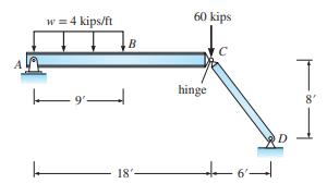
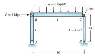
Compute the vertical and horizontal deflection at \(B\) and at the midspan of member \(C D\) in Figure P8.38.Consider both axial and bending deformations. Given: \(E=29,000 \mathrm{kips} / \mathrm{in} .^{2}, I=180 \mathrm{in} .{ }^{4}\), area of column \(=6 \mathrm{in} .^{2}\), area of girder \(=10
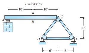
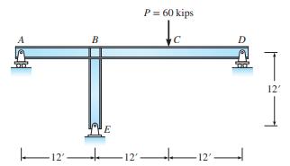
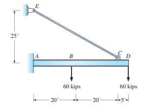
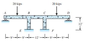
Beam \(A B C\) is supported by a three-bar truss at point \(C\) and at \(A\) by an elastomeric pad that is equivalent to a roller. (a) Compute the vertical deflection of point \(B\) in Figure P8.39 due to the applied load. (b) Compute the change in length of member \(D E\) required to displace
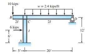
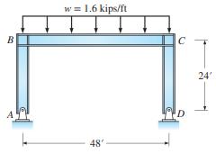
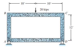
If the horizontal displacement of joint \(B\) of the frame in Figure P8.40 is not to exceed 0.36 in., what is the required \(I\) of the members? Bar \(C D\) has an area of \(4 \mathrm{in}^{2}\), and \(E=29,000 \mathrm{kips} / \mathrm{in} .^{2}\). Consider only the bending deformations of members
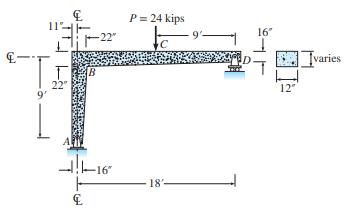
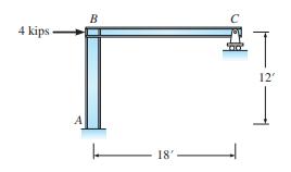
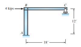
For the steel frame in Figure P8.41, compute the horizontal displacement of joint \(B\). For member \(B C D\), \(A=6000 \mathrm{~mm}^{2}\) and \(I=600 \times 10^{6} \mathrm{~mm}^{4}\). For member \(A B\), \(A=3000 \mathrm{~mm}^{2} . E=200 \mathrm{GPa}\) for all members.This note applies to Problems
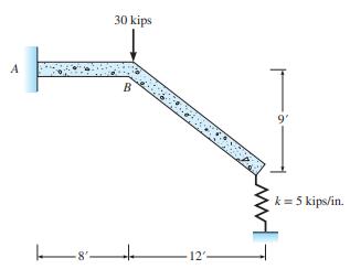
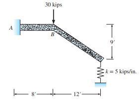
Using a finite summation, compute the initial deflection at midspan for the beam in Figure P8.42.Given: \(E=3000 \mathrm{kips} / \mathrm{in}{ }^{2}\). Use 3 -ft segments. Assume \(I=0.5 I_{G}\). A 30 kips B 12'- 9' k = 5 kips/in.
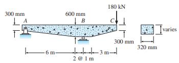
Using a finite summation, compute the initial deflection at point \(C\) for the tapered beam in Figure P8.43.\(E=24 \mathrm{GPa}\). Base your analysis on the properties of \(0.5 I_{G}\). 300 mm 6 m- 600 mm B 2 @ 1m 180 KN 300 mm H 320 mm varies
Computer study-Influence of supports on frame behavior. (a) Using the RISA-2D computer program, compute the initial elastic deflection at midspan of the girder in Figure P8.44, given that the support at \(D\) is a roller. For the computer analysis, replace the tapered members by 3 -ft-long segments
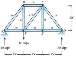
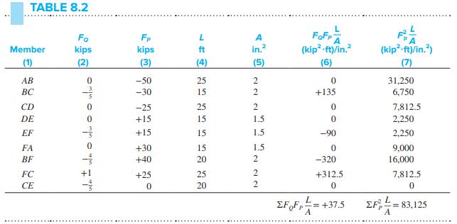
Computer study—Truss Stiffening Strategy. For the truss in Example 8.7, use the RISA-2D computer program to (a) Recompute the vertical deflection of F if the areas of members BC, CD, DE, EF, FA, FC, and CE are doubled. What is the percent increase in total volume of material used? What is
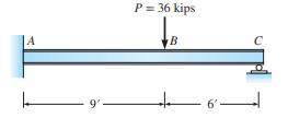
Compute the reactions, draw the shear and moment curves, and locate the point of maximum deflection for the beam in Figure P9.1.EI is constant. A 9'- P = 36 kips B
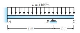
For the beam in Figure P9.2, compute the reactions, draw the shear and moment curves, and compute the deflection of the hinge at \(C\). Use \(E=29,000 \mathrm{ksi}\) and \(I=180\) in. \({ }^{4}\). A L w = 4 kN/m -8 m- B C
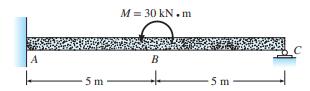
Compute the reactions and draw the shear and moment curves for the beam in Figure P9.3.EI is constant. A 5 m M= 30 kN.m B 5 m C
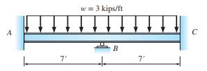
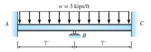
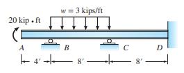
Compute the reactions for the beam in Figure P9.4.\(E I\) is constant. Use support \(B\) as the redundant. A 7' w = 3 kips/ft B 7' C
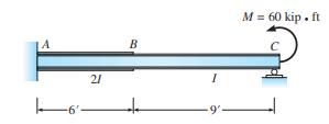
Compute the reactions, draw the shear and moment curves, and locate the point of maximum deflection for the beam in Figure P9.5.Repeat the computation if \(I\) is constant over the entire length. \(E\) is constant. Express answer in terms of \(E, I\), and \(L\). -6 21 B I 9- M = 60 kip. ft
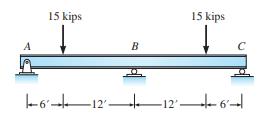
Compute the reactions and draw the shear and moment curves for the beam in Figure P9.6.EI is constant. 15 kips B 15 kips 612126
Recompute the reactions, draw the shear and moment curves for the beam in Figure P9.6 if support \(B\) settles by \(1.5 \mathrm{in}\).. Check and compare your answer to that obtained using RISA-2D, and compare the change in reaction when \(B\) settles by 0.75 in., 3.0 in. What do you observe?Figure
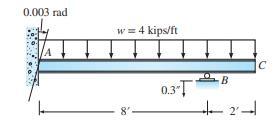
Determine the reactions for the beam in Figure P9.8.When the uniform load is applied, the fixed support rotates clockwise \(0.003 \mathrm{rad}\) and support \(B\) settles 0.3 in. Given: \(E=30,000\) kips/in. \({ }^{2}, I=240\) in. \({ }^{4}\). 0.003 rad A w = 4 kips/ft 8'- 0.31 B +2 C
(a) Recompute the reactions, draw the shear and moment curves for the beam in Figure P9.8 if segment \(A B\) has 1.5I. (b) Using RISA-2D, recompute the reactions and generate the shear and moment curves when segment \(A B\) has \(2 E I\). (c) Repeat (b) if segment \(A B\) has \(2.5 E I\).Figure
(a) Solve Problem P9.1 for the loading shown if support \(C\) settles 0.25 in. when the load is applied. Use moment at support \(A\) as the redundant. Given: \(E=30,000\) kips/in. \({ }^{2}\) and \(I=320 \mathrm{in} .{ }^{4}\). (b) Using RISA-2D, compare the result if \(I=640 \mathrm{in} .{
Assuming that no load acts, compute the reactions and draw the shear and moment curves for the beam in Figure P9.1 if support \(A\) settles 0.5 in. and support \(C\) settles 0.75 in. Given: \(E=29,000\) kips/in. \({ }^{2}\) and \(I=150\) in. \({ }^{4}\).Figure P9.1 A 9 P = 36 kips B
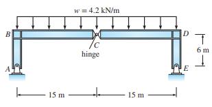
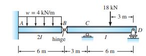
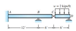
Compute the reactions and draw the shear and moment curves for the beam in Figure P9.12.\(E\) is constant. w = 4 kN/m 21 6 m- B hinge C +3m+ 18 KN 1 -3m- 6 m D
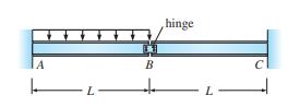
Compute the reactions and draw the shear and moment curves for the beam in Figure P9.13.EI is constant. The bolted web connection at \(B\) may be assumed to act as a hinge. Use the shear at hinge \(B\) as the redundant. Express answer in terms of \(E, I, L\), and \(w\). A L B hinge L
(a) Determine the reactions and draw the shear and moment curves for the beam in Figure P9.14.Given: \(E I\) is constant, \(E=30,000 \mathrm{kips} / \mathrm{in} .^{2}\), and \(I=288 \mathrm{in} .{ }^{4}\). (b) Repeat the computations if, in addition to the applied loads, support \(B\) settles 0.5
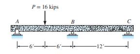
(a) Compute all reactions for the beam in Figure P9.15 assuming that the supports do not move; EI is constant. (b) Repeat computations given that support \(C\) moves upward a distance of \(288 /(E I)\) when the load is applied. P = 16 kips -6 B -12'-
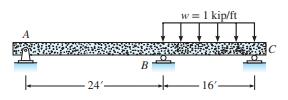
Determine all reactions and draw the shear and moment curves for the beam in Figure P9.16.EI is constant. 24'- B w = 1 kip/ft 16 C
(a) Assuming that no loads act in Figure P9.16, compute the reactions if support \(B\) is constructed 0.48 in. too low. Given: \(E=29,000 \mathrm{kips} / \mathrm{in} .{ }^{2}, I=300 \mathrm{in} .{ }^{4}\). (b) If support \(B\) settles \(\frac{3}{2}\) in. under the applied loads, compute the
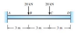
Compute the reactions and draw the shear and moment curves for the beam in Figure P9.18.Given: EI is constant. Take advantage of symmetry and use the end moment as the redundant. m 20 KN B 3 m 20 kN C 3 m
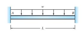
Compute the reactions and draw the shear and moment curves for the beam in Figure P9.19.Given: EI is constant. Use the reactions at \(B\) as the redundants. A W L B
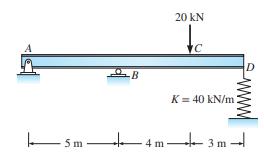
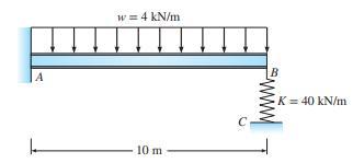
Compute the reactions and draw the shear and moment curves for the beam in Figure P9.20.Given: \(E I\) is constant for the beam. \(E=200 \mathrm{GPa}, I=40 \times 10^{6} \mathrm{~mm}^{4}\). 5m. B 20 KN C K = 40 kN/m 4m-3m-
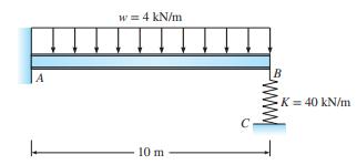
Compute the reactions and draw the shear and moment curves for the beam in Figure P9.21.In addition to the applied load, the support at \(C\) settles by \(0.1 \mathrm{~m}\). \(E I\) is constant for the beam. \(E=200 \mathrm{GPa}, I=60 \times 10^{6} \mathrm{~mm}^{4}\). A w = 4 kN/m 10 m B K = 40 kN/m
Consider the beam in Figure P9.21 without the applied load and support settlement. Compute the reactions and draw the shear and moment curves for the beam if support \(A\) rotates clockwise by \(0.005 \mathrm{rad}\).Figure P9.21 A w = 4 kN/m 10 m B K = 40 kN/m
Recompute the reactions for the beam in Figure 9.4 if a spring with \(K=235 \mathrm{kips} / \mathrm{in}\). is provided between support \(B\) and the midspan of the beam.Figure 9.4 A 7' w = 3 kips/ft B 7' C
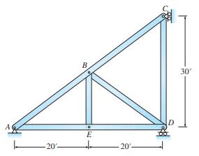
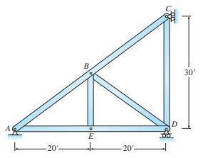
Consider the truss in Figure P9.24 without theapplied load. Determine the reactions and all bar forces for the truss if member \(A B\) is fabricated 0.25 in. too short. The area of all bars is \(5 \mathrm{in}^{2}\) and \(E\) is \(30,000 \mathrm{ksi}\). AC 20- B E to 20%- D 30'
Compute the reactions and bar forces in all members for the truss in Figure P9.24 if a downward load of 120 kips is applied at joint \(E\). The area of all bars is 5 in. \(^{2}\) and \(E=30,000\) kips/in. \({ }^{2}\).Figure P9.24 AC 20- B. E to -20% D 30'
Assuming that the 120-kip load is removed from the truss in Figure P9.24, compute the reactions and bar forces if the temperature of bars \(A B\) and \(B C\) increases \(60^{\circ} \mathrm{F}\); the coefficient of temperature expansion \(\alpha=6 \times 10^{-6}\) (in./in.) \(/{ }^{\circ}
For the trusses in Figure P9. 27, compute the reactions and bar forces produced by the applied loads. Given: \(A E=\) constant, \(A=1000 \mathrm{~mm}^{2}\), and \(E=200 \mathrm{GPa}\). A 30 kN 8 m B D 18 KN 8 m T 4 m 2 m
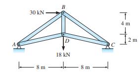
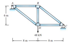
For the trusses in Figure P9. 28, compute the reactions and bar forces produced by the applied loads. Given: \(A E=\) constant, \(A=1000 \mathrm{~mm}^{2}\), and \(E=200 \mathrm{GPa}\). 6 m 8m B D 48 KN + 8 m T C
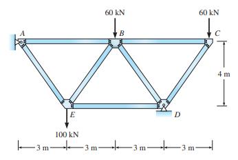
For the trusses in Figure P9. 29, compute the reactions and bar forces produced by the applied loads. Given: \(A E=\) constant, \(A=1000 \mathrm{~mm}^{2}\), and \(E=200 \mathrm{GPa}\). E 100 KN 60 KN B D 60 KN 4 m
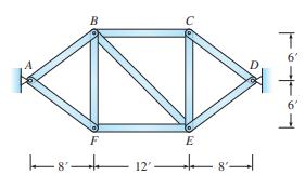
Determine the reactions and bar forces that are created in the truss in Figure P9.30 when the top chords \((A B C D)\) are subjected to a \(50^{\circ} \mathrm{F}\) temperature increase. Given: \(A E\) is constant for all bars, \(A=10\) in. \(^{2}, E=30,000\) kips/in. \({ }^{2}\), and \(\alpha=6.5
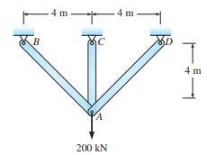
Determine the vertical and horizontal displacements at \(A\) of the pin-connected structure in Figure P9.31.Given: \(E=200 \mathrm{GPa}\) and \(A=500 \mathrm{~mm}^{2}\) for all members. -4m. B C A 200 KN -4m- XD T - 4m
Determine the vertical and horizontal displacements at \(A\) of the pin-connected structure in Figure P9.31.Given: \(E=200 \mathrm{GPa}, A_{A B}=1000 \mathrm{~mm}^{2}\), and \(A_{A C}=\) \(A_{A D}=500 \mathrm{~mm}^{2}\).Figure P9.31 B -4 m C A 200 KN -4 m- D T 4m
(a) Determine all reactions and bar forces produced by the applied load in Figure P9.33.(b) If support \(B\) settles \(1 \mathrm{in}\). and support \(C\) settles \(0.5 \mathrm{in}\). while the load acts, recompute the reactions and bar forces. For all bars the area \(=2\) in. \({ }^{2}\) and
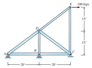
Determine the reactions and all bar forces for the truss in Figure P9.34.\(E=29,000 \mathrm{ksi}\) and members \(A B\), \(B C, A D\), and \(D C\) have \(A=3\) in. \(^{2}\), and members \(B D, D E\), and \(C E\) have \(A=1\) in. \(^{2}\) for all bars. 20 B 20 E 100 kips 15' 15'
Consider the truss in Figure P9.34 without the applied loads. Determine the reactions and all bar forces for the truss if supports \(A\) and \(C\) settle by 0.25 in.Figure P9.34 20%- B 20'- E 100 kips 15' 15'
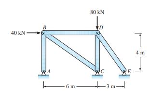
Determine the reactions and all bar forces for the truss in Figure P9.36.Given: \(E=200 \mathrm{GPa}\) and \(A=\) \(1000 \mathrm{~mm}^{2}\) for all bars. 40 KN 6 m- 80 KN D 3 E 4 m
Consider the truss in Figure P9.36 without the applied loads. Determine the reactions and all bar forces for the truss if support \(A\) settles by \(20 \mathrm{~mm}\).Figure P9.36 40 KN 6 m- 80 KN D -3m- E 4 m
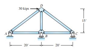
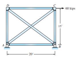
Determine all bar forces and reactions for the truss in Figure P9.38.Given: area of bar \(B D=4\) in. \(^{2}\), all other bars \(=2\) in. \(^{2}\), and \(E=30,000\) kips/in. \({ }^{2}\). D 20' 15' B 60 kips
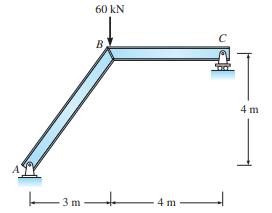
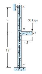
Determine the reactions at \(A\) and \(C\) in Figure P9.39.\(E I\) is constant for all members. 9' 12' A B 60 kips 4.5' D
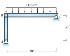
Determine all reactions for the frame in Figure P9.40 given \(I_{A B}=600\) in. \({ }^{4}, I_{B C}=900\) in. \({ }^{4}\), and \(E=29,000 \mathrm{kips} / \mathrm{in} .^{2}\). Neglect axial deformations. B A 2 kips/ft 30' C T 15'
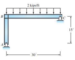
Assuming that the load is removed, compute all reactions for the frame in Figure P9.40 if member \(B C\) is fabricated \(1.2 \mathrm{in}\). too long.Figure P9.40 B A 2 kips/ft 30'- C T 15'
(a) Compute the reactions in Figure P9.42.For all members, \(E=4000 \mathrm{ksi}\) and \(I=1000\) in. \({ }^{4}\). Spring \(C D\) has a stiffness of \(5 \mathrm{kips} / \mathrm{in}\). (b) Compute the vertical deflection of joint \(B\). (c) Recompute the reaction at \(C\) if joint \(A\) settles by
Determine all reactions and draw the shear and moment diagrams for beam \(B C\) in Figure P9.43.Assume member \(A B\) has \(2 E I\) while \(B C\) has \(E I\). 4 kips A B 18' 12'
Recompute the reactions for the frame in Figure P9.43 if support \(C\) settles 0.36 in. when the load acts and support \(A\) is constructed 0.24 in. above its intended position. Given: \(E=30,000 \mathrm{kips} / \mathrm{in} .{ }^{2}\) and \(I=60 \mathrm{in} .{ }^{4}\).Figure P9.43 4 kips A B 18' 12'
(a) Determine the reactions and draw the shear and moment curves for all members of the frame in Figure P9.45.Given: \(E I=\) constant. (b) Compute the vertical deflection of the girder at point \(C\) produced by the 60-kip load. Use \(E=30,000 \mathrm{ksi}\) and \(I=600 \mathrm{in} .{ }^{4}\).
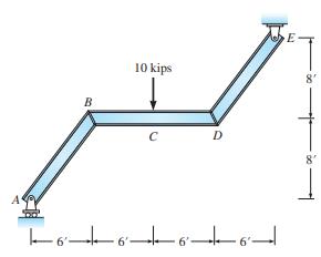
Determine the reactions at supports \(A\) and \(E\) in Figure P9.46.EI is constant for all members. B sm 100 KN C 12 m D E 8 m
Determine the reactions in the rigid frame in Figure P9.47.In addition to the applied load, the temperature of beam \(B C\) increases by \(60^{\circ} \mathrm{F}\). Given: \(I_{B C}=3600 \mathrm{in} .{ }^{4}\), \(I_{A B}=I_{C D}=1440\) in. \(.^{4}, \alpha=6.5 \times 10^{-6}\) (in./in.) \(/{
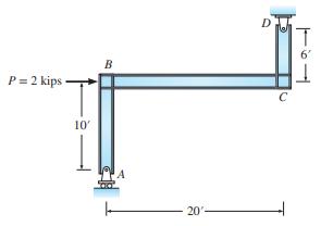
Determine the reactions at supports \(A\) and \(E\) in Figure P9.48.Area of bar \(E C=3\) in. \(^{2}, I_{A D}=400\) in. \({ }^{4}\), and \(A_{A D}=8\) in. \(^{2} ; E=30,000\) kips/in. \({ }^{2}\). 25' A 20% B 60 kips 4 20'- 60 kips +5+
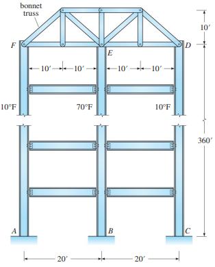
The tall building in Figure P9.49 is constructed of structural steel. The exterior columns, which are uninsulated, are exposed to the outside ambient temperature. To reduce the differential vertical displacements between the interior and exterior columns due to temperature differences between the
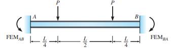
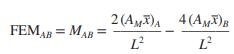
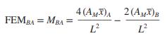
Using Equations 10.12 and 10.13, compute the fixed-end moments for the fixed-end beams. See Figures P10.1.Equations 10.12Equations 10.13 FEMAB A P ++ P B FEMBA
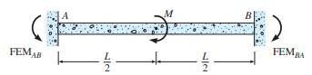
Using Equations 10.12 and 10.13, compute the fixed-end moments for the fixed-end beams. See Figures P10.2.Equations 10.12Equations 10.13 FEMAB M -- B FEMBA
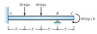
Analyze by slope-deflection and draw the shear and moment curves for the beam in Figure P10.3.Given: \(E I=\) constant. 20 kips 40 kips TT B 555 40 K 40 kip. ft
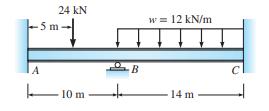
Analyze the beam in Figure P10.4 by slopedeflection and draw the shear and moment diagrams for the beam. \(E I\) is constant. 24 KN 5 m A 10 m B w = 12 kN/m 14 m
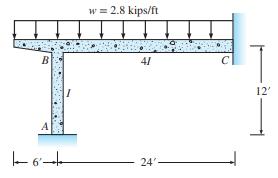
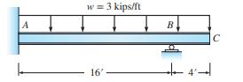
Compute the reactions at \(A\) and \(C\) in Figure P10.5.Draw the shear and moment diagram for member \(B C\). Given: \(I=2000\) in. \({ }^{4}\) and \(E=3000\) kips/in. \({ }^{2}\). B +91 w = 2.8 kips/ft 24 12'
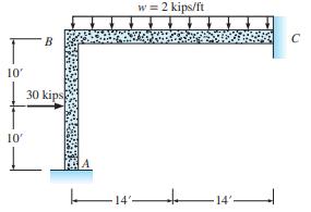
Draw the shear and moment curves for the frame in Figure P10.6.Given: \(E I\) is constant. 10' 10' B 30 kips -14 w = 2 kips/ft + 14'-
Analyze the beam in Figure P10.7.Draw the shear and moment curves. Given: \(E=29,000 \mathrm{ksi}\) and \(I=100\) in. \({ }^{4}\). 20 kip.ft A w = 3 kips/ft B |4| 8 C D
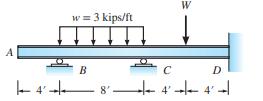
If no vertical deflection is permitted at end \(A\) for the beam in Figure P10.8, compute the required weight \(W\) that needs to be placed at midspan of \(C D\). Given: \(E=29,000\) ksi and \(I=100\) in. \({ }^{4}\). w = 3 kips/ft B 8 C W D 4-4-
(a) Under the applied loads support \(B\) in Figure P10.9 settles 0.5 in. Determine all reactions. Given: \(E=30,000 \mathrm{kips} / \mathrm{in} .^{2}\) and \(I=240 \mathrm{in} .^{4}\). (b) Compute the deflection of point \(C\). A w = 3 kips/ft 16' B C
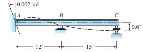
In Figure P10.10, support \(A\) rotates \(0.002 \mathrm{rad}\) and support \(C\) settles 0.6 in. Draw the shear and moment curves. Given: \(I=144\) in. \({ }^{4}\) and \(E=29,000\) kips/in. \({ }^{2}\). 10.002 rad 12 B 15- 0.6
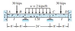
In Problems P10.11, take advantage of symmetry to simplify the analysis by slope deflection.(a) Compute all reactions and draw the shear and moment curves for the beam in Figure P10.11.Given: \(E I\) is constant. Compute the deflection at the midspan of segment \(B C\). 30 kips B w = 2 kips/ft 1.51
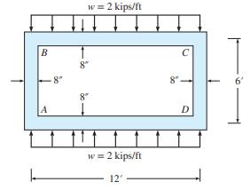
In Problems P10.12, take advantage of symmetry to simplify the analysis by slope deflection.(a) Determine the member end moments for the rectangular ring in Figure P10.12, and draw the shear and moment curves for members \(A B\) and \(A D\). The cross section of the rectangular ring is \(12
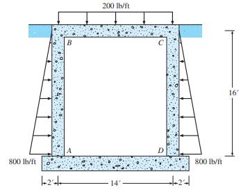
In Problems P10.13, take advantage of symmetry to simplify the analysis by slope deflection.P10.13. Figure P10.13 shows the forces exerted by the soil pressure on a typical \(1-\mathrm{ft}\) length of a concrete tunnel as well as the design load acting on the top slab. Assume that a fixed-end
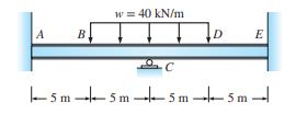
Compute the reactions and draw the shear and moment curves for the beam in Figure P10.14.Given: \(E=\) \(200 \mathrm{GPa}\) and \(I=120 \times 10^{6} \mathrm{~mm}^{4}\). A B, w = 40 kN/m C D E -5m-5m-5m-5m-
Consider the beam in Figure P10.14 without the applied load. Compute the reactions and draw the shear and moment curves for the beam if support \(C\) settles \(24 \mathrm{~mm}\) and support \(A\) rotates counterclockwise \(0.005 \mathrm{rad}\).
Analyze the frame in Figure P10.16.In addition to the applied loads, supports \(A\) and \(D\) settle by 2.16 in. \(E I=36,000 \mathrm{kip} \cdot \mathrm{ft}^{2}\) for beams and \(E I=72,000 \mathrm{kip} \cdot \mathrm{ft}^{2}\) for columns. Use symmetry to simplify the analysis. 20 kips E B 20 kips
Analyze the structure in Figure P10.17.In addition to the applied load, support \(A\) rotates clockwise by \(0.005 \mathrm{rad}\). Also \(E=200 \mathrm{GPa}\) and \(I=25 \times 10^{6} \mathrm{~mm}^{4}\) for all members. 100 KN A B 4m 1 3 m 3 m
Analyze the frame in Figure P10.18.Compute all reactions. Given: \(E I\) is constant. B 10% 10% 20 kips D 12'
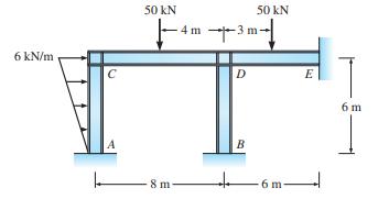
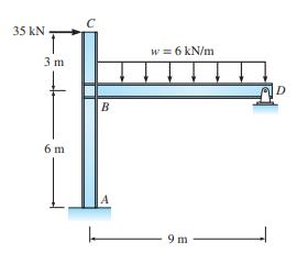
Analyze the frame in Figure P10.19.Given: EI is constant. 6 kN/m C 50 kN 8 m 4 m -3 m D 50 kN B E 6 m
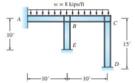
Analyze the frame in Figure P10.20.Compute all reactions. Given: \(E I\) is constant. T 10' A -10' w = 8 kips/ft + B E 10 C 15' 11.
Analyze the frame in Figure P10.20.Ignore the applied load. But support \(E\) settles by 1 in. Use \(E=\) \(29,000 \mathrm{ksi}\) and \(I=100 \mathrm{in} .^{4}\).Figure P10.20 T 10' A 10' w = 8 kips/ft + B E -10% C IID D 15'
Compute the reactions and draw the shear and moment diagrams for beam \(B D\) in Figure P10.22.\(E I\) is constant. 35 kN 3 m 6 m C B w = 6 kN/m 9m D
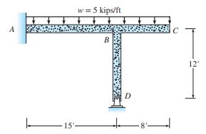
Analyze the frame in Figure P10.23.Compute the reactions and draw the shear and moment diagrams for members \(A B\) and \(B D\). Given: \(E I\) is constant. A w = 5 kips/ft 15- B D 12'
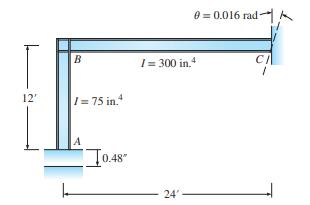
If support \(A\) in Figure P10.24 is constructed 0.48 in. too low and the support at \(C\) is accidentally constructed at a slope of \(0.016 \mathrm{rad}\) clockwise from a vertical axis through \(C\), determine the moment and reactions created when the structure is connected to its supports.
Showing 300 - 400
of 570
1
2
3
4
5
6
Step by Step Answers