New Semester
Started
Get
50% OFF
Study Help!
--h --m --s
Claim Now
Question Answers
Textbooks
Find textbooks, questions and answers
Oops, something went wrong!
Change your search query and then try again
S
Books
FREE
Study Help
Expert Questions
Accounting
General Management
Mathematics
Finance
Organizational Behaviour
Law
Physics
Operating System
Management Leadership
Sociology
Programming
Marketing
Database
Computer Network
Economics
Textbooks Solutions
Accounting
Managerial Accounting
Management Leadership
Cost Accounting
Statistics
Business Law
Corporate Finance
Finance
Economics
Auditing
Tutors
Online Tutors
Find a Tutor
Hire a Tutor
Become a Tutor
AI Tutor
AI Study Planner
NEW
Sell Books
Search
Search
Sign In
Register
study help
engineering
introduction to electrical power
Introduction To Electrical Power And Power Electronics 1st Edition Mukund R. Patel - Solutions
Determine the rms value of voltage induced in a 30-turn coil on a 20 × 20 cm cross-section core with peak flux density of 1.65 T alternating at 50 Hz.
In a single-phase switchboard, two parallel rectangular bus bars 1.1 in. apart at center lines experience 20,000 Arms current when a load gets short-circuit fault. Determine the peak mechanical force per foot length of the bus bars. Assume the bus bar shape factor K = 0.8. State whether this force
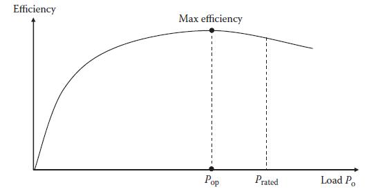
An electrical machine has a no-load loss of 10 kW and a full-load loss of 26 kW when delivering 500 kW. Determine its (1) full-load efficiency and (2) maximum efficiency with the corresponding load point in percentage of the full load and in kilowatts. Efficiency Max efficiency Pop Prated Load Po
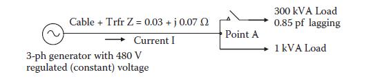
A three-phase, 480-V, 5000-kVA generator connects to many feeders, one of which takes single-phase power to two equipment at the other end (see figure below) via a cable and transformer with combined Z = 0.03 + j0.07 Ω. The voltage at point A at the receiving end rises and falls as a large
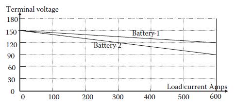
Battery-1 and Battery-2 have their terminal voltage versus load current droop lines shown in the following figure. Determine analytically the load current shared by each battery and the battery bus voltage if they share a total load current of (1) 900 A and (2) 600 A. In case of a 600-A total load,
A cable is designed for 30-year life with 50°C rise in 40°C ambient air at rated load. If it is continuously overloaded by 15%, determine its new expected life.
The stator winding insulation resistance of a 100-hp, 460-V motor was measured to be 10 MΩ when sitting idle in normal room temperature of 20°C. Determine whether this motor is worthy of connecting to the line as per the IEEE Standard.
A 50-hp, 240-V dc motor runs at 2350 rpm at rated conditions. If its field current is decreased by 20% while keeping the load current the same, determine its approximate and exact speed.
A single-phase, 100-kVA, 460/120-V transformer with 3% R and 6% X is powering a 3-KW heater. Determine the total continuous circuit impedance in ohms looking from the source side and the current drawn from the source.
A three-phase, 460-V, 60-Hz, 500-hp induction motor has a design efficiency of 92% and pf of 0.80 lagging. The cable reactance from the control center to the motor is 0.015 Ω/ph. If the motor pf were corrected to unity by placing capacitors next to the motor, determine the % voltage rise at the
A three-phase, 150-hp, 460-V, letter code L induction motor is started directly from 480-V lines. The source impedance and the cable impedance add up to a total of 0.01 + j0.02 Ω/phase. If the starting pf of the motor is 0.25 lagging, determine the exact and approximate voltage drops in percentage
Two rectangular copper bus bars, each 8 mm thick × 100 mm wide with facing flats, are separated by 10-mm space between the flats. Determine per meter run of the bus bars: (1) The resistance and leakage inductance at 75°C and (2) The mechanical force under a fault current of 35 kA peak, assuming
Determine the % voltage regulation of a 100-kVA, 480/120-V distribution system having total impedance ZTotal = (2 + j9) % delivering 90% load at 0.8 pf lagging. Make your calculations using per unit values.
A 60-Hz single-phase cable having inductance of 0.3 μH/m and resistance of 2.5 mΩ/m is delivering 100 kW at 2400 V and 0.85 pf lagging. The load is 40 m away from the generator. Determine the generator terminal voltage rise on removing this load.
A new 1000-kW, Δ-connected, 440-V, 60-Hz induction motor is proposed on your job. On a direct line start, it would draw 10 × rated current and cause transient voltage sag of 15%, which is unacceptable. Determine the line voltage sag with a Y–Δ starter.
A power distribution center serves single-phase load via cable and a 50-kVA 277/120-V step-down transformer. Based on the transformer kilovoltampere rating, the cable impedance is 2 + j1%, and the transformer impedance is 1 + j5%. The equipment is drawing 75% load at 86.6% power factor lagging.
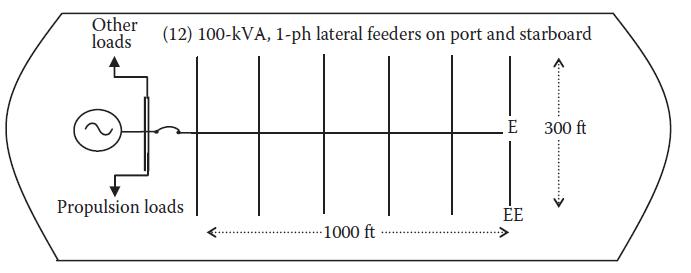
In a cruise ship that is 1000 ft. long and 300 ft. wide, a three-phase, 4160-V main feeder from the generator switchboard distributes 1200-kVA hotel load to 12 sectors fed by single-phase, 100-kVA, 120-V lateral feeders as shown in the following figure. Each junction of the main feeder and the
In a power distribution system from the generator to a pump, various equipment efficiencies are given as follows: generator 95%, transformer 97%, cable 99%, motor 94%, and pump 93%, all in series. If the pump output is 1000 hp, determine the contribution of this pump on the prime mover’s output
A 20-kHz high-power cable has a 10-mm conductor diameter. Determine its approximate Rac/Rdc ratio if it is (1) Made of one solid conductor, (2) Made of numerous thin conductor strands that are not insulated from each other, and (3) Made of Litz cable. Use the concept of skin depth in your
An industrial process heater delivers power from a 480-V dc generator to a 30-Ω load resistance that produces 7680-W heat when fully on. A reduced operation requires only 4224 W of average heat generation rate. Determine (1) The required series rheostat resistance and the process energy
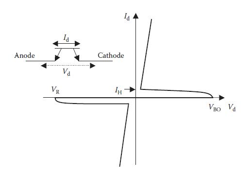
Explain the difference between the diode and the thyristor in construction and in operation.
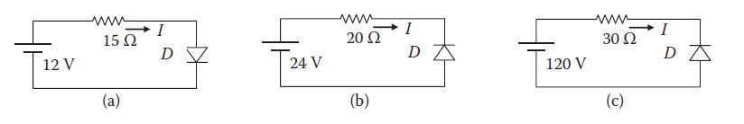
Determine the current, voltage, and power loss in the diodes of circuits (a), (b), and (c) shown in the figure below, where all diodes have a forward voltage drop of 0.8 V and reverse breakdown voltage of 50 V. 12 V Μ 15 Ω (a) I D 24 V www 20 Ω (b) Ι DA 120 V www 30 Ω (c) I DZ
A 240-V dc generator is powering a chemical process heater that has 20-Ω load resistance and produces 2880-W heat when fully on. A certain operation requires a partial heat of only 2160W on average. Determine:(1) The required series resistance (rheostat) value and the process energy efficiency
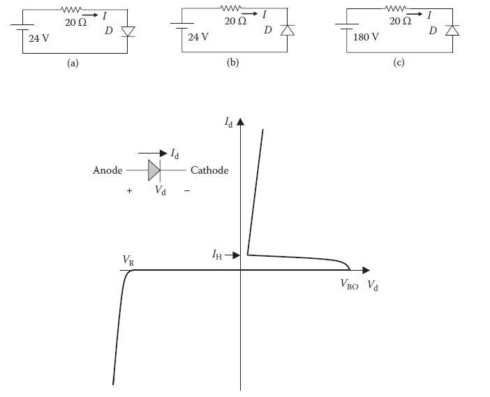
Determine the current, voltage, and power loss in the diodes of circuits (a), (b), and (c) shown below, where all diodes have a forward voltage drop of 1 V and reverse breakdown voltage of 100 V. 24 V wwww 20 Ω (a) I D Anode + VR 24 V ww 20 (2 Ін (b) la Cathode DA 180 V VBO Vd www 2002 (c) I DZ
In what two different ways can the transistor be used in electronic circuits?
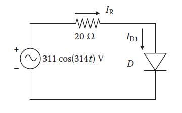
With ideal diodes (zero forward voltage drop and high reverse breakdown voltage) in the figure below, determine the average power absorbed by the resistor. + 1 www 20 Ω ~311 cos(314t) V IR IDI ↓ D Z
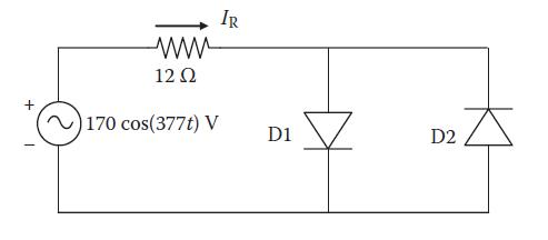
For the circuit shown below with ideal diodes (zero forward voltage drop and high reverse breakdown voltage), determine the average power absorbed by the resistor. + T 12 Q2 ~170 cos (377t) V IR D1 D2
Differentiate the terms switching speed and switching frequency.
A thyristor in a certain 240-V converter design can see a maximum forward voltage of 120 VLNrms. Its data sheet specifies a maximum allowable di/dt of 80 A/μs. Determine the snubber inductor you must include in the converter design to limit di/dt to 60 A/μs to allow for the desired margin.
High di/dt causes what, high voltage stress or high current stress? Why?
A thyristor in a certain 440-V converter design can see a maximum forward voltage of 254 VLNrms. Its data sheet specifies a maximum allowable di/dt of 100 A/μs. Determine the snubber inductor you must include in the converter design to limit the di/dt stress to 70 A/μs to allow for a desired
A power electronics device builds up the voltage from 0 to 120 V in 180 μs and turns off 100 A in 250 μs. Determine the dv/dt and di/dt stresses on the device.
High dv/dt causes what, high voltage stress or high current stress? Why?
A power electronics device turns off 50 A in 200 μs and builds up the voltage from zero to 110 V in 220 μs. Determine the di/dt and dv/dt stresses on the device.
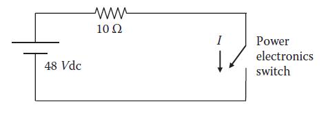
In the circuit shown below, the power electronics switch is operating at 2000-Hz switching frequency with a 50% duty ratio. The switch has an on- state voltage drop of 0.8 V, off-state leakage current 2 mA in reverse bias, switch-on time 1.5 μs, and switch-off time 2.0 μs. Determine the average
In the circuit below, the power electronics switch is operating at 1000-Hz switching frequency with a 60% duty ratio. The switch has on-state voltage drop of 1 V, off-state leakage current of 1.5 mA in reverse bias, switch-on time of 1.2 μs, and switch-off time of 1.5 μs. Determine the average
When would you need to rerate (derate or uprate) a device and for what reason?
A buck converter operating at 50-Hz switching frequency has Ton = 5 ms. Determine the average source current if the load current is 40A.
A buck converter is operating at 1-kHz switching frequency from a 120-V dc source. The inductance is 50 mH. If the output voltage is 60 V and the load resistance is 12 Ω, we determine the following: Duty ratio D = 60 V ÷ 120 V = 0.50 period T = 1/1000 = 0.001 s = 1 ms. Ton = 0.50 × 1 = 0.5
Explain the principle on which the buck converter analysis is based.
A buck converter has 120-V input voltage, RL = 12 Ω, switching frequency of 1 kHz, and on-time of 0.5 ms. If the average source current is 2 A, we determine the following:For 1-kHz switching frequency, T = 1/1000 s = 1 ms, duty ratio = 0.5/1 = 0.5, Ton = 0.5 ms, and Toff = 1 – 0.5 = 0.5 ms
As the duty ratio changes from 0.1 to 0.9, how does the buck–boost converter voltage ratio change?
At what duty ratio does the buck–boost converter change from buck to boost?
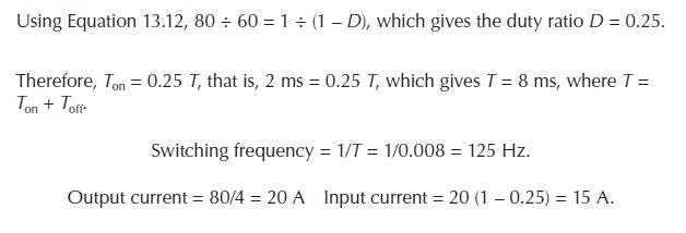
A boost converter powers a 4-Ω resistor and 1-mH inductor load. The input voltage is 60 V, and the output load voltage is 80 V. If the on-time is 2 ms, we determine the following.Equation 13.12, Using Equation 13.12, 80 ÷ 60 = 1 ÷ (1-D), which gives the duty ratio D = 0.25. Therefore, Ton = 0.25
For a buck converter with Vout = 5 V, fs = 20 kHz, L = 1 mH, C = 470 μF, Vin = 12.6 V, and Iout = 0.2 A, determine the peak-to-peak ripple ΔVout in the output voltage.
What does the term electrical isolation mean? How is it achieved in a converter design?
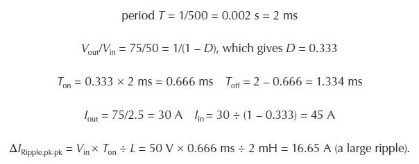
For a boost converter with switching frequency of 500 Hz, input of 50 V dc, output of 75 V dc, inductor of 2 mH, and load resistance of 2.5 Ω, we determine the following: period T = 1/500 = 0.002 s= 2 ms Vout/Vin = 75/50 = 1/(1-D), which gives D = 0.333 Ton = 0.333 x 2 ms = 0.666 ms Toff = 2-0.666
Identify the similarities and differences between the dc–dc converter and the ac transformer.
Identify the construction and functional differences between the transformer and the inductor.
What flies back in the flyback converter?
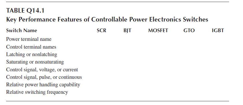
Fill in the table below with the key performance features of controllable power electronics switches covered in this chapter. TABLE Q14.1 Key Performance Features of Controllable Power Electronics Switches SCR MOSFET GTO Switch Name Power terminal name Control terminal names Latching or
Identify and explain the benefit of using high frequency switching in the switch-mode power converter design.
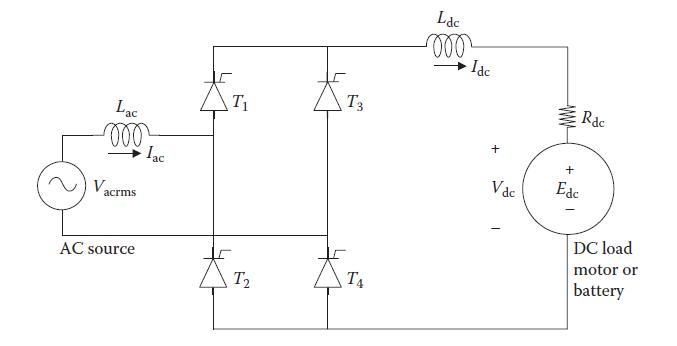
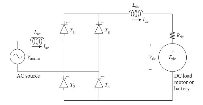
A single-phase full-wave rectifier shown in Figure 14.1 is built using diodes and a large inductor. Determine the average and rms values of the current in each diode.Figure 14.1 Lac -000 V₂ acrms AC source Iac T₁ T2 T3 TA Ldc 000 Idc + Vdc ww Rac + Edc DC load motor or battery
A single-phase full-wave rectifier shown in Figure 14.1 is built using a thy-ristors. Determine the average and rms values of the current in each thyristor when the firing delay angle α = 0 and the input voltage is (1) 240-V, 50-Hz ac, or (2) 120-V, 60-Hz ac.Figure 14.1 Lac moo Vacrms AC
The rectifier of Example 14.2 with the ac side cable inductance of 2 mH and the dc side cable resistance of 0.5 Ω is charging a battery at 5.4-A charge rate instead of powering the 10-Ω resistance. Determine the voltage available at the battery terminal.Data from example 14.2A single-phase
What is the difference between the term's ripples and harmonics?
A single-phase full-wave bridge rectifier using phase-controlled thyristors with a large Ldc converts 60 Hz, 120 V rms to dc for a dc side load resistance of 10 Ω. For the firing delay angle α = 60°, determine the dc side voltage and the power absorbed by the load, ignoring the cable inductances
A single-phase full-bridge bridge rectifier using phase-controlled thyristors with a large Ldc converts 50-Hz, 240-V rms to dc for a dc side load resistance of 12 Ω. For the firing delay angle α = 30°, determine the dc side voltage and the power absorbed by the load, ignoring the cable
Explain the difference between the firing delay angle α and the commutation delay angle u.
The rectifier of Example 14.2 with the ac side cable inductance of 3 mH and the dc side cable resistance of 1.0 Ω is charging a battery at a 10-A charge rate instead of powering the 10-Ω resistance. Determine the voltage available at the battery terminal.Data from Example 14.2A single-phase
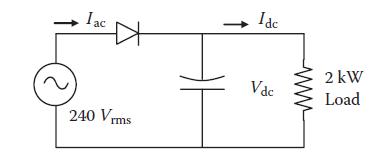
A single-phase half-wave diode rectifier draws power from a single-phase, 240-V, 60-Hz source and delivers to a 2-kW load on the dc side at constant voltage Vdc with a large filter capacitor as shown in the figure below. The ac side harmonics to fundamental current ratios Ih/I1 in percentage are
Identify the source of the load power factor, displacement power factor, and harmonic power factor.
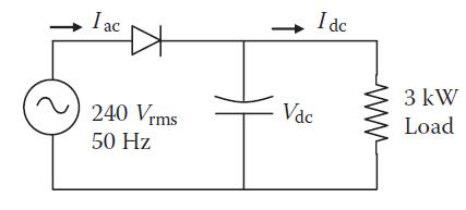
A half-wave diode rectifier draws power from a single-phase, 240-V, 50-Hz source and delivers to a 3-kW load on the dc side at constant voltage Vdc with a large filter capacitor as shown in the figure below. The ac side harmonics to fundamental current ratios Ih/I1 in percentage are 80, 40, 10, 6,
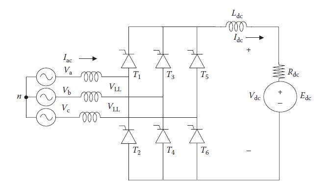
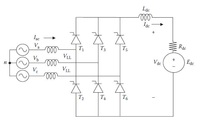
A three-phase, full-bridge, six-pulse rectifier shown in Figure 14.4 is built with diodes and a large inductor. Determine the average and rms values of the current in each diode.Figure 14.4 o V₂ fo n Vb V₂ 000 000 Z VLL VLL T2 Z T3 T4 T5 T6 Ldc -000 Ide + Vdc + I Rac Ede
What is the principal difference between CSI and VSI?
A 460-V, three-phase, full-bridge, six-pulse rectifier shown in Figure 14.4 is built with diodes and a large inductor. Determine the average and rms values of the current in each diode if the output load current is: (1) 50-A dc and(2) 135-A dc.Figure 14.4
Explain the difference between the snubber circuit and the commutation circuit.
A three-phase six-pulse thyristor rectifier with a large dc side filter inductor delivers 500-kW power at 525 V dc and draws 60-Hz power from 460 VLL via a cable with leakage inductance of 25 μH. Determine the thyristor’s commutation angle.
A three-phase, six-pulse thyristor rectifier with a large dc side filter inductor delivers 200-kW power at 240-V dc and draws 60-Hz power from 220 VLL via a cable with leakage inductance of 30 μH. Determine the thyristor’s firing delay angle and the commutation angle.
Decades ago, large uninterruptible power supply design in ac systems used an ac electrical machine coupled to a dc machine connecting to a battery to convert the ac into dc and vice versa. Draw such an electromechanical UPS schematic incorporating the ac bus and the user loads. Today, the
A three-phase six-pulse voltage source inverter (VSI) is fed with 240 V dc. Determine the ac side rms fundamental line-to-line voltage and the first four harmonic voltages.
A three-phase six-pulse VSI is fed with 480-V dc. Determine the ac side rms fundamental line-to-line voltage and the first four harmonic voltages.
A three-phase six-pulse CSI is fed from a 240-V dc bus with a dc-link current of 80 A. The ac side load has 0.85 power factor lagging. Determine the ac side rms phase and line currents and output phase and line voltages.
A three-phase six-pulse CSI is fed from a 120-V dc bus with dc-link current of 60 A. The ac side load has 0.90 power factor lagging. Determine the ac side rms values of(1) Phase and line currents and (2) Phase and line voltages.
Determine the dc-link voltage for a variable frequency drive (VFD) to drive a three-phase 460-V induction motor.
Determine the dc-link voltage for a variable frequency drive (VFD) to drive a three-phase 6600-V induction motor for ship propulsion.
A three-phase, 1000-hp, eight-pole, 50-Hz synchronous motor uses a cycloconverter to vary speed. Determine the maximum speed it can be operated at to limit the harmonics to the generally acceptable level.
A 3-ph, 5000-hp, 12-pole, 60-Hz synchronous motor uses a cycloconverter to vary speed. Determine the maximum speed at which it can be operated to limit the harmonics to the generally acceptable level.
Why is the ac universally adopted for the electrical power grid over dc?
The electrical potential of point 1 is 3000 V higher than that of point 2. If 200 C of charge per minute flows from point 1 to 2, determine the current and power flow from point 1 to 2 and the energy transferred in 15 min.
The electrical potential of point A is 200 V higher than that of point B, and 30 C of charge per minute flows from A to b. Determine the current and power flow from A to B and the energy transferred in 1 min.
Why is the three-phase power system universally adopted over a single-phase ac power system?
A sinusoidal voltage of 900 cos 377t volts applied across a circuit element draws 250 cos(377t – 30°) amperes. Determine the average power absorbed in the element.
A circuit element has sinusoidal voltage of 300 cos 314t volts across its terminals and draws 80 cos (314t – 25°) amperes. Determine the average power delivered to the element.
Explain the terms phasor, phase difference, and operator j.
For two phasors à = 85∠40° and B̃ = 700∠50°, find (i) à + B̃ , (ii) à − B̃ , (iii) Ã × B̃ , and (iv) Ã/B̃ . Express each result in θ -form and also in θ-form.
Given two phasors, Ã = 60∠30° and B̃ = 40∠ 60°, determine (1) Ã + B̃, (2) Ã − B̃ , (3) Ã × B̃, and (4) Ã/B̃. Express each result in j-form and also in θ-form.General note:For simplicity in writing, all angles we write following ∠ signs in this book are in degrees, whether or
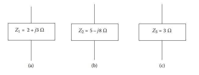
For the impedance boxes Z1, Z2, and Z3 shown below, which of the R, L, and C element(s) and their relative magnitudes, can you expect to see if you open the boxes? Answer for each box individually. Z = 2 + j3 Ω (a) Zy = 5 -j8 Ω (b) Z3 = 3 Ω (c)
If phasor à = 8.5/j6.5, express it in j-form, θ-form, and e-form.
A source voltage of 240 Vrms is applied to 30∠30° Ω load impedance. Find the average current, rms current, peak current, and average power delivered to the load.
A one-loop circuit has source voltage of 120 V and load impedance of 10∠+84.3º Ω. Determine the current and average power delivered to the load. Can you guess about the nature of the load—could it be a heater, capacitor, motor, etc.?
If a 50-Hz impedance box of value 10∠−30° Ω designed to work on a 240-V, 50-Hz source in Europe is connected to a 240-V, 60-Hz source in the United States, how would the current magnitude and phase angle change at higher frequency (will they increase or decrease?)
A coil having inductance of 30 mH and resistance of 3 Ω is connected to a 120-V, 60-Hz source. Determine the kilowatt-hour energy drawn by the coil in an 8-h period.
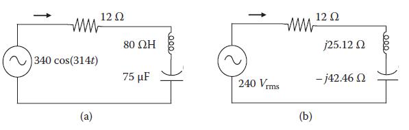
Convert the time-domain circuit shown in figure (a) below in the phasor domain with impedances in ohms. Then, determine the current phasor Ĩ and the average power. 340 cos(314t) 12 Ω 80 ΩΗ 75 με 240 Vrms www (b) 12 Ω j25.12 Ω - j42.46 Ω .000
Determine the average real power drawn by a coil having inductance of 10 mH and resistance of 1.5 Ω connected to a 120-V, 60-Hz source.
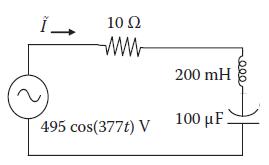
The figure below is in time domain. Express it in phasor domain with impedances in ohms, and determine the current phasor and the average power. 10 Ω 200 mH 495 cos(377t) V 100 Ε. 20007
What is the complex conjugate of a current, and why is the conjugate (and not the straight) current used to determine the complex power in ac circuits?
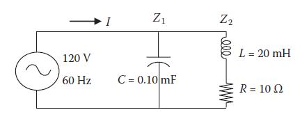
A 120-V, 60-Hz, single-phase source shown below powers a 0.10-mF capacitor in parallel with 20-mH coil that has 10-Ω winding resistance. Determine the current, pf, and power delivered by the source. (Practical capacitors have negligible resistance, but the inductors have significant resistance due
If the real power from the source to the load delivers real work (pumps water, ventilates air, heats space, etc.), what does the reactive power do?
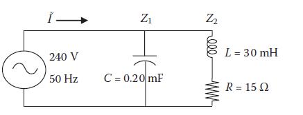
A 240-V, 50-Hz, single-phase voltage is applied to the circuit shown in the figure below. Determine the current, pf, and power delivered by the source. 1- 240 V 50 Hz Z₁ C = 0.20 mF Z₂ S rell L = 30 mH R = 15 Ω
Showing 100 - 200
of 476
1
2
3
4
5
Step by Step Answers